
555 light tester circuit diagram
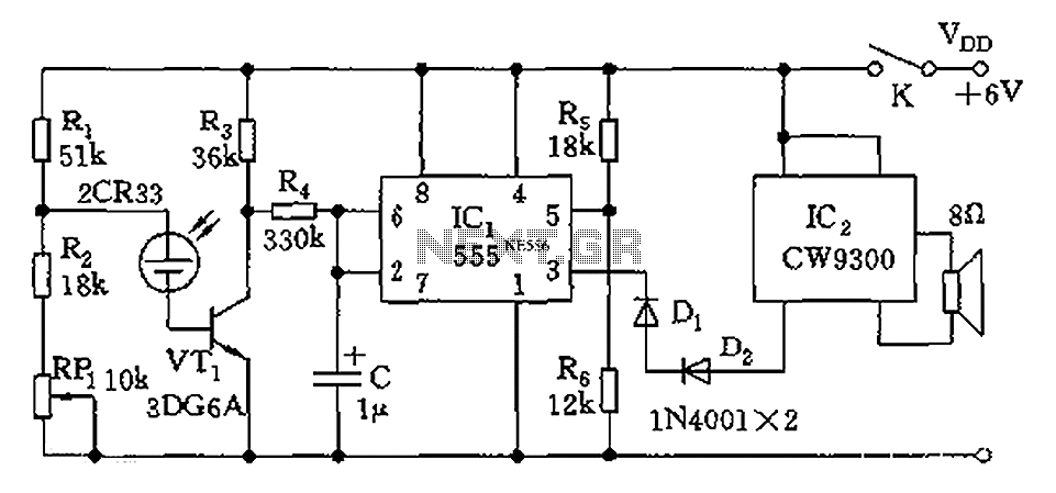
The described circuit employs a combination of photoelectric sensors and a 555 timer integrated circuit to achieve sound activation based on ambient light levels. The primary sensor, a photovoltaic cell (2CR33), serves as a light-dependent resistor, altering its resistance based on the intensity of light it receives. Under conditions of illumination below 100 lux, which is deemed optimal for learning environments, the resistance of the 2CR33 increases significantly. This increase leads to the turn-off of transistor VT1, which in turn causes the 555 timer to enter a reset state.
In this reset state, the output at pin 3 of the 555 timer drops to a low level. The low output effectively prevents the music IC (9300) from generating sound. The design allows for a responsive mechanism where the 9300 IC is only activated when sufficient light is present. The testing procedure involved the use of a 15W bulb positioned at a distance of 0.3 meters, which successfully produced an illumination level of about 100 lux.
To achieve the desired sensitivity, a variable resistor (RP1) is incorporated into the circuit. This component allows for the adjustment of the threshold level, enabling the user to calibrate the circuit to activate the sound output at varying light levels. By carefully tuning RP1, the circuit can be set to a point where the music IC remains silent until the light intensity surpasses the 100 lux threshold, at which point the sound is triggered. This adaptability makes the circuit suitable for various applications, including educational tools and interactive installations where sound feedback is required in response to lighting conditions. As shown constituting the photoelectric conversion by the photoelectric sensors and switches 555, etc., issued by a music song to prompt IC2. Illuminance sensor parts are made of photovoltaic cells 2CR33. When light is lower than the most suitable for learning 100 lux illumination, 2CR33 was high resistance, VT1 off nearly 555 was 2 feet high (greater than 1/3Vdd 2V), 555 in the reset state, 3 feet was low, music IC2 (9300) issued by the sound of music was electric. When debugging, the 15W light bulb for the light from the lamp 0.3m battery in place, its illumination of about 100 lux.
Adjust RP1, make 9300 just does not sound, shifting slightly farther away, the sound.
Related Circuits

This application involves a static switch circuit where the control logic is implemented using a flip-flop, which is driven by a unijunction transistor. The flashing rate of the circuit can be adjusted, ranging from approximately 0.1 seconds to a...
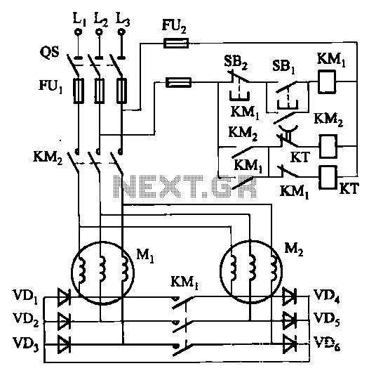
The circuit depicted in Figure 3-157 is designed for motors with a capacity of no more than 11 kW, requiring precise stopping capabilities. Upon shutdown, contact KMi releases, and the motor stator windings are configured into a three-phase rectifier...

Dual power for each load refers to the operation of two power supplies working simultaneously to handle the electrical load. In the event of a power outage, a contact switch automatically closes all load circuits that are not powered...
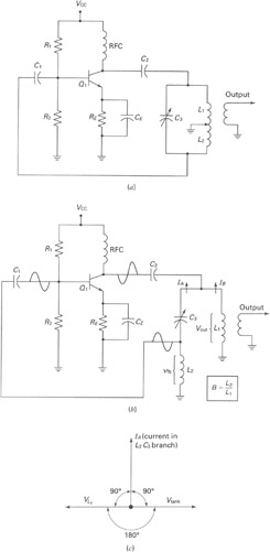
A widely recognized circuit is the Hartley oscillator, which is characterized by a tapped coil within the LC tank circuit. The tap point of the coil is grounded. The oscillator's amplifier section functions as a common-emitter amplifier, resulting in...
This circuit is a 1024 kHz temperature-compensated crystal oscillator. The circuit theory is illustrated. Due to the low output signal level of the circuit, a buffer using the following transistor VT1 is implemented for amplification. The base bias resistor...
Second Stage Joule Thief Circuits The second stage Joule Thief circuit is an advanced iteration of the basic Joule Thief design, which is primarily used to extract energy from low-voltage sources, such as depleted batteries. This circuit is particularly effective...