
Thermal electromagnetic circuit long delay over-current release

The DK series control boxes are designed for robust electrical protection in various applications. The thermal electromagnetic overcurrent release mechanism is a critical component that protects against excessive current conditions, which can lead to equipment damage or fire hazards. The overload protection feature ensures that the circuit remains operational under normal load conditions while providing a delay to avoid nuisance tripping during temporary overloads.
The instantaneous short circuit protection is designed to react quickly to fault conditions, allowing for immediate disconnection of the circuit to prevent damage. The long delay feature is particularly useful in applications where inrush currents may occur, allowing the system to tolerate brief overload conditions without interruption.
The quick saturation current transformer (TA) plays a vital role in sensing current levels and providing accurate feedback to the control circuitry. The shunt (F) is utilized to bypass the buckle coils, enabling a controlled response during fault conditions. The sub-gate button (SBi) allows for manual intervention in the control process, providing operators with the ability to reset or test the system as necessary.
The thermal relay (FR) monitors the temperature of the system, ensuring that overheating conditions are detected and addressed promptly. The circuit breaker (QF) serves as a primary protective device, automatically interrupting the circuit in the event of a fault. Auxiliary contacts provide additional functionality, such as signaling or interlocking with other systems, enhancing the overall reliability and safety of the control box.
Overall, the DK-5A, 5D, and SDb control boxes provide comprehensive protection and control for electrical systems, ensuring safe and efficient operation in various industrial and commercial applications.DK-5A, 5D, SDb control box, all with a thermal electromagnetic overcurrent release, the circuit shown in Figure 6-80. Trip has overload and short circuit instantaneous action l ong delay protection. Figure, TA is quick saturation current transformer, F to shunt off the buckle coils, SBi as the sub-gate button, FR thermal relay, QF circuit breaker and auxiliary contacts.
Related Circuits
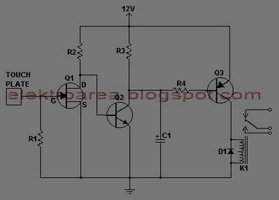
This document describes a series of touch switches that utilize only three transistors. These touch-based transistor switches can activate a load simply by the user touching a metal plate. They are designed to directly switch a relay, enabling operation...
The circuit employs an infrared (IR) phototransistor, designated as Q1, to sense the IR output signal from a remote control. The output from Q1 is then amplified by a PNP transistor, labeled Q2, which activates LED1. This illumination indicates...
The figure illustrates a simple project schematic of a metronome. A metronome is a device utilized by musicians to produce continuous beats through a speaker. The metronome circuit typically consists of several key components that work together to generate a...
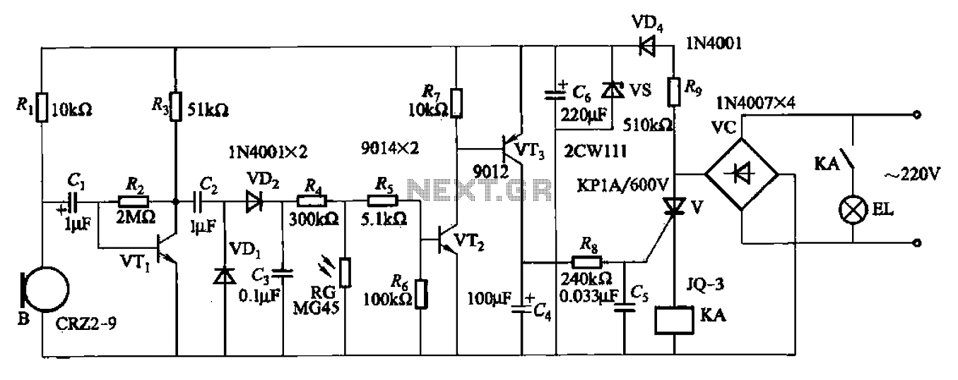
A resistor R8, capacitors Cd, and a thyristor V AC switch form a delay circuit. The lamp's lighting delay time is determined by the resistor Rs and capacitor C4, with a delay of approximately 40 seconds as indicated in...

The circuit operates using two 741 operational amplifiers and achieves a gain exceeding 20 dB in each channel. Utilizing a higher-quality op-amp can improve the noise figure and bandwidth. Additionally, the circuit features a sharp roll-off at 20,000 Hertz. This...
The transmitter provides an optical link (infrared) for headphones. Three infrared LEDs (IR) are powered by T1, with P1 used to adjust the current level. The current consumption of this headphones infrared transmitter is approximately 60mA at 9V. The infrared...