
Stroboscope with 555 timer

The circuit described utilizes the NE555 timer IC configured in astable multivibrator mode to generate a rectangular pulse signal, which is instrumental for synchronizing the observation of movement between multiple stroboscopes. The frequency of oscillation can be adjusted within a range of 2Hz to 20Hz using a variable resistor (potentiometer) designated as P1. This feature allows for flexibility in the stroboscopic effect, which can be tailored to the specific application or observation requirements.
Power supply for the circuit is derived from a low voltage transformer (TR1), which steps down the mains voltage to a suitable level for the circuit's operation. The output from the transformer is then rectified using a traditional bridge rectifier configuration, followed by voltage regulation through a zener diode, ensuring a stable and adequate power supply for the NE555 timer and other components.
The design allows for the control potentiometer P1 to be placed up to 30 meters away from the main circuit. This remote adjustment capability is particularly useful in applications where the stroboscope needs to be operated from a distance, enhancing usability and safety.
Components TR2, TR3, and TR4 may be specialized transformers that could be less commonly available in standard electronic stores, which may necessitate sourcing from specific suppliers or manufacturers. Caution is advised when handling the circuit, particularly around capacitors C5, C7, and C9, as these components can hold high voltages that pose a safety risk. Proper precautions and safety measures should be observed to prevent electrical shock or damage to the circuit.This circuit enables observation of movement between other stroboscopes. Generation of rectangular signal is based on NE555. This circuit requires a low power supply that is made from a simple transformer TR1, traditional rectifier bridge and zener diode. NE555 works in multivibrator mode generating astable pulses of 2Hz to 20Hz. The frequency is adjusted by potentiometer P1. The control potentiometer P1 can be placed as far as 30 meters away, for suspension of stroboscope’s work from far away.
It is east to find all parts with facility in every electronic store, but it may be difficult to find the transformers TR2, TR3, TR4. Take extreme care handling this circuit because near C5-C7-C9 high voltages are present. 🔗 External reference
Related Circuits
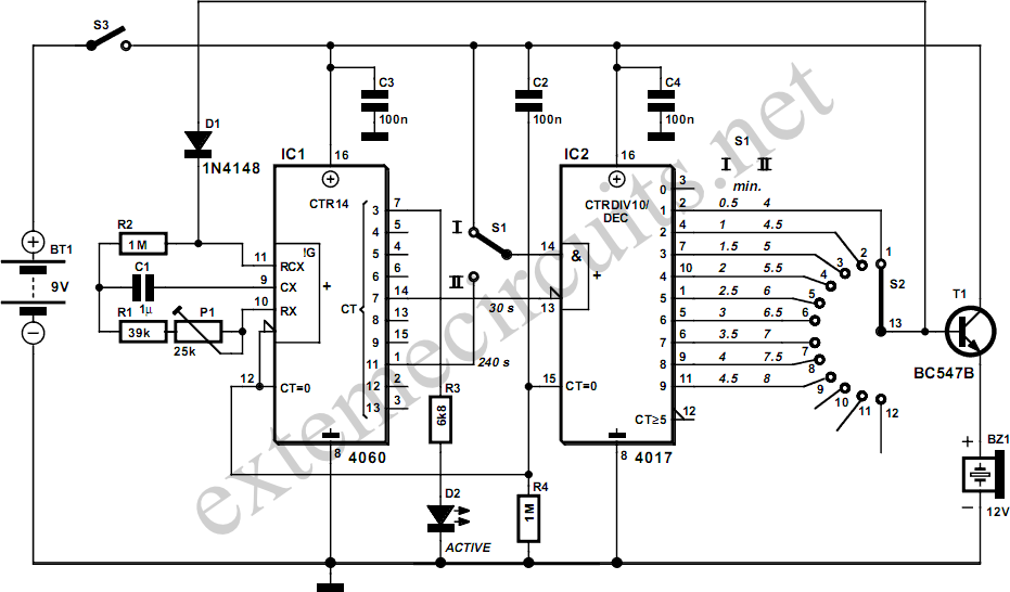
This egg timer is a simple and functional circuit that demonstrates that microcontrollers are not always necessary. It consists of two integrated circuits (ICs) from the standard 4000 logic family, a multi-position rotary switch, and a few discrete components....
The time is set by potentiometer R2, which provides a range from 1 second to 100 seconds, using a timing capacitor C1 of 100 µF. The output at pin 3 is normally low, keeping the relay in the off...

The QAMI5516 is an integrated demodulator and decoder solution designed for digital cable receivers, capable of handling compressed video, audio, and data services. This QAM demodulator executes intermediate frequency (IF) to MPEG-2 block processing of QAM carriers. The resulting...
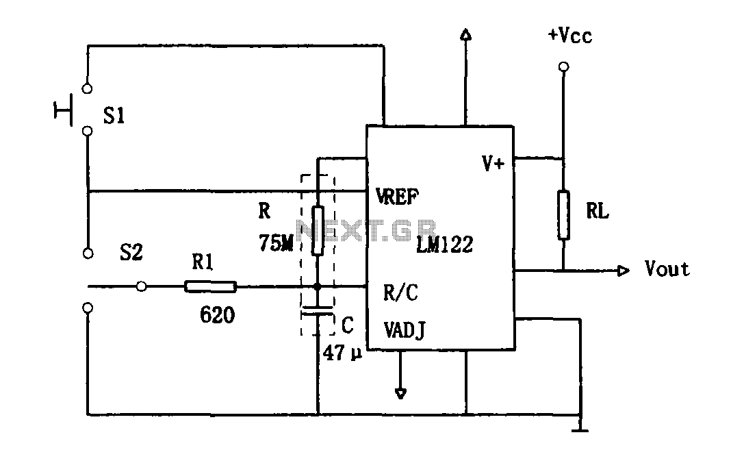
As illustrated in Figure 1, the circuit utilizes an LM122 timer. The circuit's start, reset, and stop functions are managed through switching operations. Switch S1 initiates the timing sequence when the timer is activated; thereafter, this switch has no...
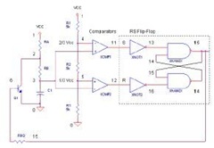
The 555 Timer IC operates in three modes: monostable, astable, and bistable/Schmitt trigger. This article will focus on its astable mode. The astable mode of the 555 Timer IC is characterized by its ability to generate a continuous square wave...
A simple astable timer made with the 555 timer IC allows independent adjustment of the mark (on) and space (off) values. The timing circuit comprises resistors Ra, Rb, and capacitor Ct. The capacitor Ct charges through resistor Ra, which...