
Structure and working principles of various protective circuit diagram e

The protection circuit for large scale integration (LSI) devices is essential to safeguard against abnormal voltage levels that can occur due to various input signal conditions. The circuit typically includes a combination of diodes, resistors, and capacitors designed to redirect excess voltage away from sensitive components within the LSI.
When an abnormal voltage is detected at the input pin, the protection circuit activates, providing a low-resistance path to ground or to the power supply rail, thereby preventing damage to the internal circuitry. The diodes are often configured in a clamping arrangement, allowing them to conduct when the voltage exceeds a certain threshold, effectively shunting the excess voltage.
Furthermore, the design of the protection circuit must consider the response time and the maximum voltage levels that the LSI can tolerate. Capacitors may be employed to filter out high-frequency noise, ensuring that transient spikes do not reach the internal circuits. The choice of components is critical; for instance, fast-switching diodes are preferred to minimize delay in response to voltage surges.
In summary, the protection circuit serves as a crucial line of defense for LSI circuits, ensuring their reliability and longevity by managing abnormal voltage conditions effectively. The principles of operation are based on well-established electronic components and configurations that work together to maintain the integrity of the LSI's functionality.Due to the different circumstances of the various input signals, when the pin is applied between the abnormal voltage, protection circuits to form a circuit path from while LSI (large scale integration) circuits internal protection. Structure and principles of its protection circuit is shown
Related Circuits
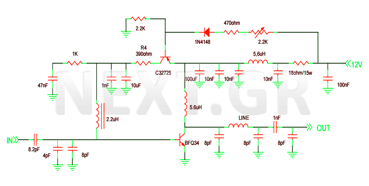
This project involves the construction of a VHF-UHF linear amplifier capable of operating at frequencies ranging from 47 MHz to 740 MHz. It serves as the final output stage for any transmitter functioning within these frequencies. The amplifier utilizes...
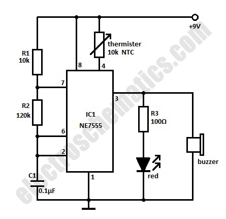
The high-temperature alarm will emit a beep and the LED will blink when the temperature of the device rises abnormally. This simple overheating alarm is designed to monitor heat levels. The high-temperature alarm circuit is an essential safety device used...
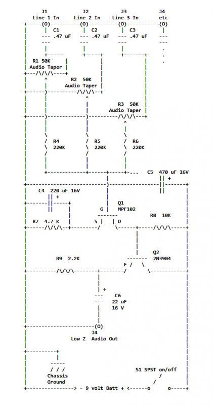
If two of these circuits are made in the same enclosure for stereo, then there can be a single power supply to run both of them. There should be a resistor in series with the incoming 9V+ lead so...
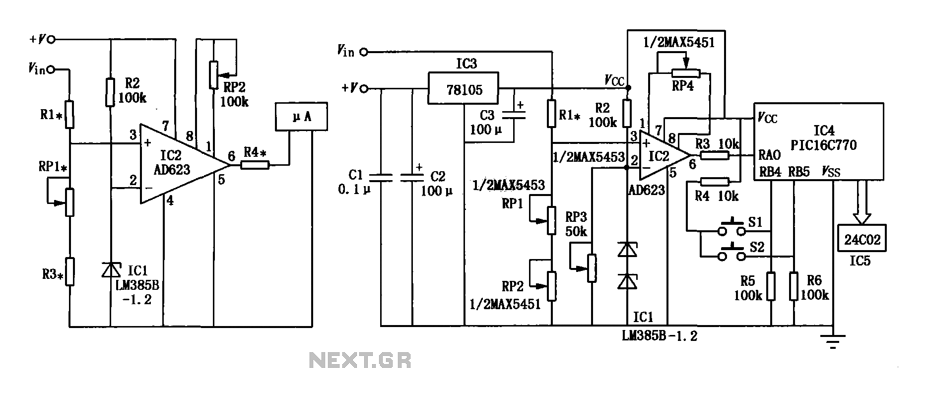
The range precision voltmeter electrical schematic is depicted in Figure (a) below. It features an amplifier circuit and several high-precision components that significantly enhance the performance range of the voltmeter. The inverting input of the instrumentation amplifier AD623 (IC2)...
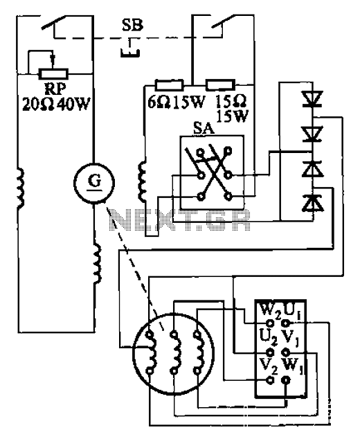
The AX3-300-2 DC arc welding machine circuit is part of the AX, AX1, AX3, and AR series of rotary DC arc welding machines. These machines share a similar structural design, featuring a three-integral unit configuration that combines an inverter...
The Implantable Lamp (A3024) is a radio-controlled lamp powered by a battery. Once encapsulated in epoxy and silicone, it is waterproof and compact, allowing it to be implanted in an animal. The A3024 can theoretically be activated by any...