
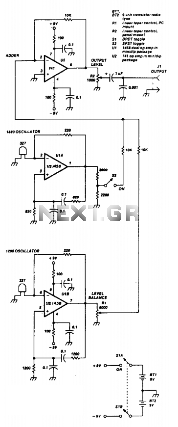
Subaudible tone encoder

The twin-T oscillator is a specific type of electronic oscillator that utilizes a twin-T network configuration to produce audio signals at subaudible frequencies. The circuit typically consists of two T-shaped networks composed of resistors and capacitors, which are configured to create phase shifts necessary for oscillation.
In this design, the oscillator is capable of producing six different frequencies, specifically within the range of 93 Hz to 170 Hz. The selection of these frequencies is achieved through the adjustment of component values or through the use of switches that alter the resistor and capacitor configurations, enabling the user to choose from three distinct frequency ranges.
The operation of the twin-T oscillator is based on the principle of feedback, where a portion of the output signal is fed back into the input in a manner that sustains oscillation. The stability and accuracy of the generated frequencies are influenced by the tolerance of the components used, particularly the resistors and capacitors, as well as the quality of the power supply.
In practical applications, such oscillators can be utilized in sound synthesis, alarm systems, and various audio applications where low-frequency tones are required. The ability to produce multiple preset tones makes this oscillator versatile for different uses, including experimental sound design and audio testing. Proper grounding and shielding are essential in the circuit design to minimize unwanted noise and ensure signal integrity.This twin-T oscillator produces six preset subaudible tones from 93 to 170 Hz in three ranges.
Related Circuits
Two 741 operational amplifiers serve as the active components in this Wien bridge oscillator configuration. The dual version of the 741, known as the 1458, can also be utilized. The frequencies of the two oscillators are selected to correspond...
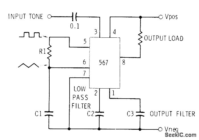
This circuit can be utilized for Touch-Tone decoding as well as for telephone line and wireless control applications using a single audio frequency. The operating center frequency is determined by components H1 and C1. The resistor R1 should be...
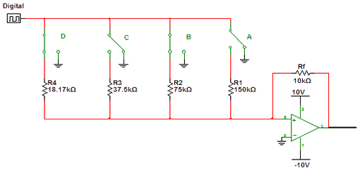
Encoders and decoders are circuits that convert analog signals to digital signals and digital signals to analog signals. The input is in digital form, while the output is a continuous sine wave or analog wave. Encoders and decoders play a...
A newcomer is seeking a welcoming environment and expresses a desire to share a considerable amount of information. In the context of electronic schematics, it is essential to facilitate an inclusive environment for individuals at all levels of expertise. This...
The LM1036 is a DC-controlled circuit designed for adjusting tone (bass and treble), volume, and balance in stereo applications such as car radios, televisions, and audio systems. It features an additional control input for straightforward loudness compensation. The circuit...
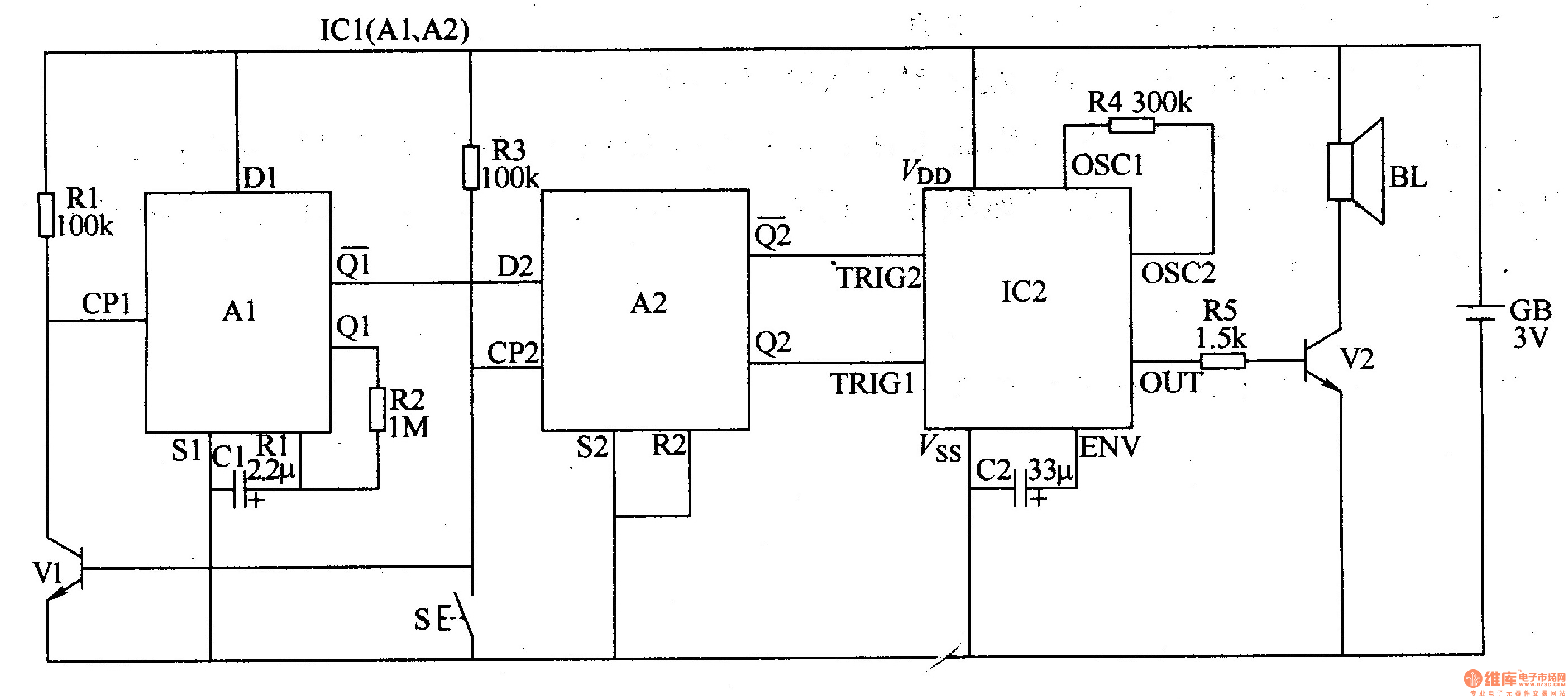
The two-tone electronic doorbell circuit consists of an input trigger circuit and an audio output circuit. The input trigger circuit includes a doorbell button (S), a transistor (V1), resistors (R1-R3), a capacitor (C1), and a dual D flip-flop integrated...