
Using the MAX4929E for HDMI/DVI Low-Frequency Switching

The MAX4929E is a specialized integrated circuit designed for seamless switching in HDMI and DVI applications. It is crucial for maintaining signal integrity while protecting sensitive components from electrostatic discharge (ESD). The device operates by routing low-frequency signals, which are essential for the proper functioning of HDMI/DVI communication, through its internal switching mechanism. This ensures that the selected input source is efficiently connected to the output without degradation of signal quality.
The ESD protection feature of the MAX4929E is particularly important in environments where external connections may be exposed to static electricity or other transient voltage spikes. By incorporating high-level ESD protection, the device safeguards the HDMI/DVI interface from potential damage, thus enhancing the reliability and longevity of the overall system.
In terms of interfacing, the MAX4929E is designed to work with an EDID EPROM. It accepts a 5V input signal, which is a common voltage level in digital communication, and provides a clamped output of 3.3V. This output voltage level aligns with the requirements of the EDID standard, ensuring compatibility with various display devices. The clamping function is vital as it prevents higher voltage levels from damaging the EDID circuitry.
Additionally, the MAX4929E addresses the issue of capacitance in the DDC (Display Data Channel) lines. By removing the capacitance from one of the lines, the device ensures that only one set of DDC connections is active at a time. This feature is essential for maintaining clear communication between the source and display, preventing signal interference and ensuring accurate data transfer.
Overall, the MAX4929E serves as a robust solution for HDMI/DVI switching applications, combining efficient signal management with essential protection features to enhance system performance and reliability.This application notes describes how the MAX4929E takes care of switching all low frequency signals (LoF) needed for a 2:1 HDMI/DVI switch while adding high level ESD protection to all outside lines, and how MAX4929E mates with an EDID EPROM, accepting 5V signal levels at the input and clamping the output to 3.3 V to match the EDID. In addition it removes the capacitance of one of the lines, so the DDC output only has one set of DDC connections at a time..
🔗 External reference
Related Circuits

This liquid level sensor circuit employs a common operational amplifier IC 741 configured as a comparator. When the sensor detects that the two fluid levels (which can be represented by two small pieces of PCB or similar conductors) are...
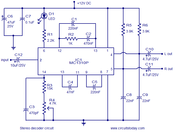
A simple FM stereo decoder circuit utilizing the MC1310P integrated circuit (IC). It operates at 12V and provides a channel separation of 40dB, making it suitable for stereo FM receivers. The FM stereo decoder circuit based on the MC1310P IC...
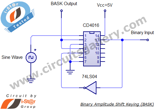
Binary Amplitude Shift Keying (BASK), also known as On-Off Keying (OOK), is a digital modulation technique where the amplitude of the carrier signal is altered according to binary data. This modulation scheme is utilized for transmitting digital information over...
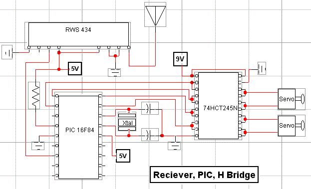
RF technology is an exciting field to incorporate into electronic designs. However, for beginners, constructing reliable RF transmitters and receivers can be challenging. RF (Radio Frequency) technology plays a crucial role in modern communication systems, enabling wireless data transmission over...
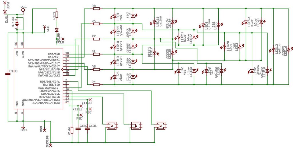
Microdot - wrist watch LED pattern timepiece. This project is a circuit board designed for creating a wristwatch-sized version. The Microdot wristwatch project involves the design and implementation of a compact circuit board that integrates LED technology to display time...
An adjustable laboratory power supply capable of providing an output voltage range from 0 to 60 volts can be constructed using the provided circuit diagram. This power supply can utilize the LM723 chip for lower voltage applications or, for...