
Supply Voltage Indicator

The circuit operates on a voltage monitoring principle using a combination of resistors, capacitors, and a microcontroller or a simple comparator circuit to control the behavior of LED1. The power supply voltage is monitored continuously, and the circuit is designed to operate within a specific voltage range.
When the input voltage is at 12 volts, the circuit maintains a steady state where LED1 is illuminated continuously. This is achieved through a direct connection from the power supply to the LED, ensuring that the voltage drop across the LED is sufficient to keep it lit.
As the voltage begins to drop below 11 volts, the circuit transitions to a blinking mode. This is typically implemented using a timing circuit, which could be based on a 555 timer configured in astable mode, or using a microcontroller programmed to toggle the LED at a specific frequency. The frequency of blinking decreases as the voltage continues to drop, providing a visual cue that the voltage is falling. The blink rate can be adjusted through component selection, such as changing resistor or capacitor values in the timing circuit.
Once the voltage reaches approximately 9 volts, the circuit is designed to turn off the LED completely. This is accomplished by either cutting off the power to the LED through a transistor or by reconfiguring the timing circuit to stop the output signal. The result is a clear and intuitive representation of the supply voltage status, allowing users to quickly assess the health of the power supply without the need for additional measurement tools.
In summary, this circuit serves as a voltage level indicator, providing visual feedback through LED1. The use of blinking and steady illumination effectively communicates the status of the supply voltage, making it a valuable tool in various electronic applications.This simple and slightly odd circuit can clearly show the level of the supply voltage (in a larger device): as long as the indicator has good 12 volts at its input, LED1 gives steady, uninterrupted (for the naked eye) yellow light. If the input voltage falls below 11 V, LED1 will start to blink and the blinking will just get slower and slower if the voltage drops further - giving very clear and intuitive representation of the supply`s status.
The blinking will stop and LED1 will finally go out at a little below 9 volts. 🔗 External reference
Related Circuits
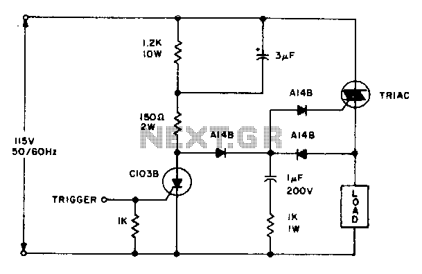
The triac will be activated at the beginning of the positive half cycle due to the current flowing through the 3 µF capacitor, provided that the C103 SCR is in the off state. The load voltage subsequently charges the...
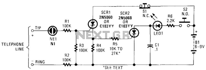
In this circuit, the ringing voltage on a telephone line causes NE-1 to break over, triggering SCR1, which in turn triggers SCR2. If a call has been received, depressing S2 will cause LED1 to light. Depressing S1 resets the...
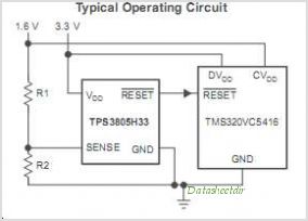
The TRF1115 is the first of two ASICs utilized in the receiver section of the Texas Instruments MMDS/MDS/WCS/802.16x chipset. This device is responsible for down-converting the input frequency to an intermediate frequency (IF) within the range of 420 MHz...
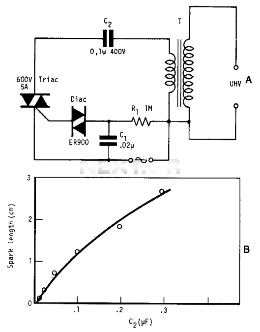
By repetitively charging and discharging a capacitor through the primary winding of an induction coil with high voltage, an ultra-high electromotive force (emf) is induced in the secondary winding. Switching is performed by a triac, which is triggered by...
The Brushless DC motor with permanent magnetism is an advanced electrical machine characterized by innovative principles and technology. It consists of three main components: the Brushless DC motor body (BLDCM), a trochanter position transducer (RPS), and a control unit...
The voltage to frequency converter (V/FC - VCO) circuit consists of a UJT (uni-junction transistor) oscillator in which the timing charge capacitor C2 is utilized. The voltage to frequency converter circuit operates by converting an input voltage into an output...