
200mA/Hour 12V NiCAD Battery Charger

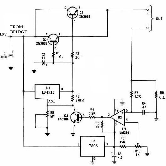
The following diagram represents a lead-acid battery charger circuit, which provides an initial voltage of 2.5 V per cell at 25 °C to facilitate rapid charging. The charging current decreases as the battery charges, and when it drops to 180 mA, the charging circuit reduces the output voltage. This regulated and adjustable battery charger circuit is capable of charging most NiCAD batteries. It is suitable for single cells or multiple battery cells connected in series or parallel, with a maximum voltage of 18 V. Power transistors Q1 and Q2 are configured as series regulators.
Additionally, a simple circuit diagram for a 12V car battery charger is available. This circuit is designed to prevent battery overcharging, which can lead to electrolyte loss due to evaporation. It monitors the battery's charge condition through a retroactive control circuit that applies a high charge when necessary. Furthermore, this battery charger circuit is intended for rechargeable lithium batteries, utilizing a constant current of 60 mA for AA cells, with a cutoff voltage of 2.4 V per cell, at which point charging must be terminated. The system is designed for multi-cell battery packs consisting of 2 to 6 series-connected cells. Lastly, a schematic diagram for a solar-powered mobile phone battery charger is provided. This circuit is engineered to charge the battery from a source with a lower voltage and should not be used to charge a battery with the same or lower voltage than that generated by the solar panel to ensure proper operation.This NiCAD battery charger circuit charges the battery at 75 mA until the battery is charged, then it reduces the current to a trickle rate. It will fully recharge a dead/unpowered battery in 4 hours and the battery can be left in the charger indefinitely.
To set the shut off point, connect a 270 ohm / 2 Watt resistor across the charge terminals a nd adjust the pot for 15. 5V across the resistor. Tags: 12V NiCAD battery Charger, 200mA/Hour NiCAD battery Charger, NiCAD battery Charger circuit, NiCAD battery Charger diagram, NiCAD battery Charger schematic, The following diagram is the schematic diagram of Ni-CAD Battery Charger circuit which featured with current and voltage limiting to keep the battery lifetime. The lamp L1 will be light brightly and the LED will be out when the battery is low and battery charging in progress, but the LED is very bright and the.
The following diagram is the circuit diagram of Lead-Acid battery charger. This circuit provides an initial voltage of 2. 5 V per cell at 25 ƒ to quickly charge the battery. The charging current decreases as the battery is charging, and when the current drops to 180 mA, the charging circuit reduces the output voltage of. This battery charger circuit is regulated and adjustable to make this circuit able to charge the mosto NiCAD battery.
This circuit will work for single cell or multi battery cell which connected with series/parallel connection. The maximum voltage of the batteries should be 18V maximum. Power transistors Q1 and Q2 are connected as series regulators. Here is a simple and easy to build circuit diagram of a 12V car battery charger: The above circuit claimed have ability to prevent battery overcharge that make electrolyte lost due to evaporation.
This circuit will eliminate the problems by monitoring the battery`s condition of charge through its retroactive control circuit by applying a high. This battery charger circuit is used for rechargable lithium battery. Charging is accomplished with a constant current of 60 mA for AA cells to a cutoff of 2. 4V per cell, at which point the charge must be terminated. The charging system shown is designed for multi-cell battery pack of 2 to 6 series connected cell. This is the schematic diagram of solar powered mobile phone battery charger. The circuit is designed to charge the battery from a source with a lower voltage. Do not use it to charge the battery with the same or lower voltage than the voltage which is generated by the solar panel.
For proper operation of. 🔗 External reference
Related Circuits
This circuit is designed to convert 12V DC into 220V AC. It utilizes a 4047 integrated circuit to generate a 50Hz square wave, which is then amplified for current and voltage using a step-up transformer. The fundamental relationship between...
This universal battery charger utilizes the LM317 voltage regulator and features an adjustable output voltage along with a constant-current charging circuit, making it suitable for charging most NiCad batteries and various other battery types. The LM317 universal battery charger...
The input transformer is likely to be the most expensive component of the entire project. Alternatively, a pair of 12 Volt car batteries could be utilized. The input voltage to the regulator must be several volts higher than the...
The above pictured schematic diagram is just a standard constant current model with a added current limiter, consisting of Q1, R1, and R4. The moment too much current is flowing biases Q1 and drops the output voltage. The output...
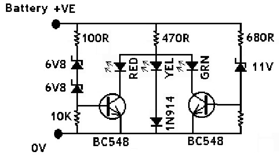
The IN914 (small glass diode) and the zener diodes have bands on their bodies that must be oriented according to the diagram provided. The bands are located at the cathode end of the diodes. A magnifying glass can assist...

This is a simple and low-cost NiCd and NiMH battery charger. The schematic diagram indicates that the charging current (I) should be set to 1/10 of the battery's rated capacity. For instance, if the battery has a rated capacity...