
Synchronization of SMPS Power Modules

The Cyclone V FPGA requires careful consideration of its power supply architecture to ensure optimal performance and reliability. The integration of multiple power modules on a single power board is a practical solution to meet the specific load requirements of the FPGA. This approach allows for the distribution of power across various voltage levels, which is essential for the different operational blocks within the FPGA.
Typically, the power board would incorporate several DC-DC converters, each tailored to supply different voltage rails as dictated by the FPGA's specifications. Common voltage levels required by Cyclone V FPGAs include 1.2V for the core, 2.5V for I/O, and 3.3V for auxiliary functions. The use of synchronous buck converters is recommended for their efficiency in converting higher input voltages down to the required levels with minimal heat generation.
The power management system should also include features such as power sequencing and monitoring to ensure that all voltage rails are stable before the FPGA begins operation. This can be achieved through the use of power management ICs (PMICs) that can coordinate the startup and shutdown sequences of the power modules.
Thermal management must also be considered, as the concentration of multiple power modules can lead to increased heat generation. Adequate heat sinking and airflow must be designed into the PCB layout to maintain operational temperatures within specified limits.
In summary, the effective integration of multiple power modules on a single power board is crucial for meeting the diverse power requirements of Cyclone V FPGAs. This design approach enhances efficiency, reliability, and performance, ensuring that the FPGA operates within its specified parameters.A Practical Application for Cyclone V FPGA Power Requirements The integration of multiple power modules on a single power board allows for specific load requirements to be.. 🔗 External reference
Related Circuits
12W Audio Power Amplifier Circuit Diagram. Features: small power amplifier, excellent sound quality, incorporates a fully integrated design. The 12W audio power amplifier circuit is designed to provide high-quality audio amplification in a compact form factor. This amplifier is capable...
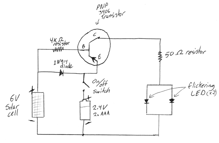
This is a DIY electronics project designed to enhance circuit design and building techniques. Copper lanterns were purchased and fitted with a circuit similar to outdoor solar lights. The circuit design is adapted from a simple design found on...

The circuit is constructed using two 555 timer integrated circuits (ICs), designated as U1 and U2. U1 is configured as a variable duty cycle oscillator with a fixed time period of approximately 0.1 seconds. The duty cycle can be...
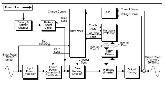
The UPS (Uninterruptible Power Supply) Reference Design offers a pre-designed uninterruptible power supply solution utilizing the flexibility of the PIC17C43 microcontroller. This microcontroller is noted for its low-cost and high-performance capabilities, which are not typically found in other microcontrollers....
This precision power supply is a valuable addition to any workbench, serving as either a primary or supplementary power supply. It offers a voltage range of 0 to 40V and a current capacity of 2A, with adjustable current limiting...
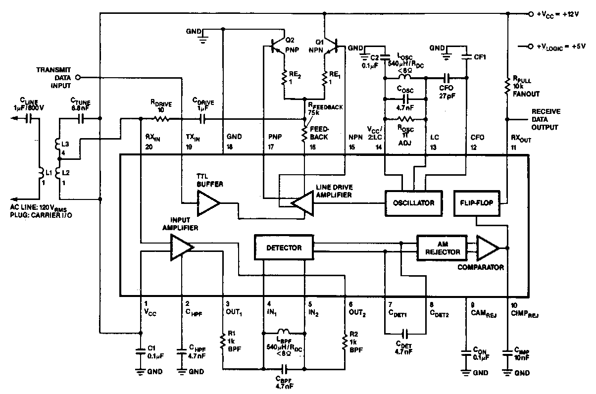
In the 100 kHz application, the coupling network connects to the receiver section located at the bottom of the chip. The external components will be summarized later. The receive data output is pulled up through a resistor (RPuLL) valued...