
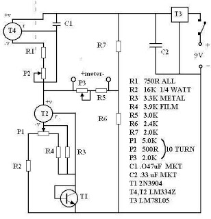
Synchronous controller circuit diagram of a recording transcript
The described system integrates multiple technologies to enhance the effectiveness of modern exhibitions. The automatic program circuit is designed to play pre-recorded audio commentary in conjunction with visual displays, creating an immersive experience for the audience. This circuit typically involves a microcontroller or programmable logic device (PLD) that manages the playback of audio files stored in a digital format.
The synchronization of two mating times is critical for ensuring that the audio commentary aligns perfectly with the visual elements of the exhibition. This can be achieved through a synchronous controller circuit, which may utilize a combination of timers, counters, and control logic to coordinate the timing of audio playback with other events in the exhibition.
The electrical diagrams for this system would include representations of the power supply, signal flow, and control logic. Key components may include audio amplifiers, speakers, and light control circuits, which are all integrated to work in unison. The use of light and sound in a synchronized manner not only captures attention but also reinforces the message being conveyed through the exhibition.
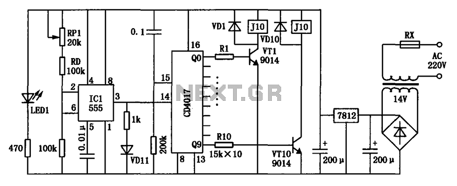
In summary, the modern exhibition circuit design incorporates advanced technologies and precise timing mechanisms to deliver a cohesive and engaging experience, making use of both electrical engineering principles and creative design to achieve its objectives.Activities Modern exhibition, advertising, promotion and propaganda extensive use of sound, light, electricity technology, a number of electrical diagrams, control model, commo nly used automatic program circuit with pre-recorded commentary, then asked the two mating time required to achieve synchronization. Shown for the recording transcript synchronous controller circuit.
Related Circuits
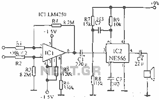
The circuit is designed for teaching demonstrations or experiments to hear the electrocardiogram (ECG) signal voltage. The ECG signal voltage is amplified by the LM4250 operational amplifier, which is connected to a voltage-controlled oscillator (NE566) to modulate the oscillator...
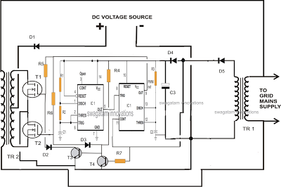
A single IC 556 has been utilized to generate PWM pulses. One half of the IC is configured as a high-frequency generator, which supplies the other half of the IC, set up as a pulse width modulator. The modulating...
DIY Intercom Circuit Full-duplex intercom circuit schematic, cable on the way to the intercom circuit. The DIY intercom circuit is designed to facilitate two-way communication using a full-duplex system. This allows simultaneous transmission and reception of audio signals, enabling clear...
There are many digital thermometers with ±1°C displays, but their accuracy is approximately ±1°C and they cannot be calibrated. A thermometer circuit was created using components available at a local electronics hobby shop, providing an educational experience. For a...
The ATMEL AVR programmer operates with the Windows program "Ponyprog," which is compatible with Windows 95, 98, and XP. The ATMEL AVR programmer is a device designed for programming AVR microcontrollers. It interfaces with the microcontroller through the ISP (In-System...
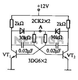
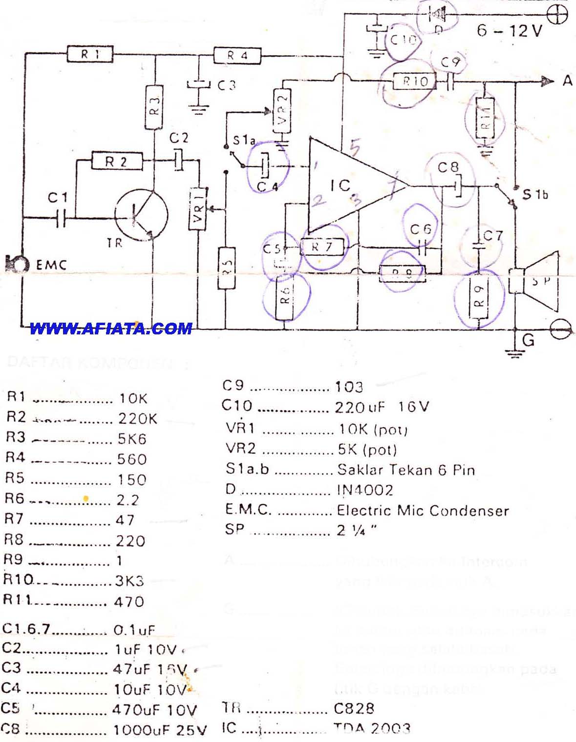
The circuit illustrated in Figure (A) consists of resistors R1 and R2 with values ranging from 15 to 18 kΩ, and capacitors C1 and C2 with capacitance values between 0.01 µF and 10 µF. Figure (B) depicts the oscillation...