
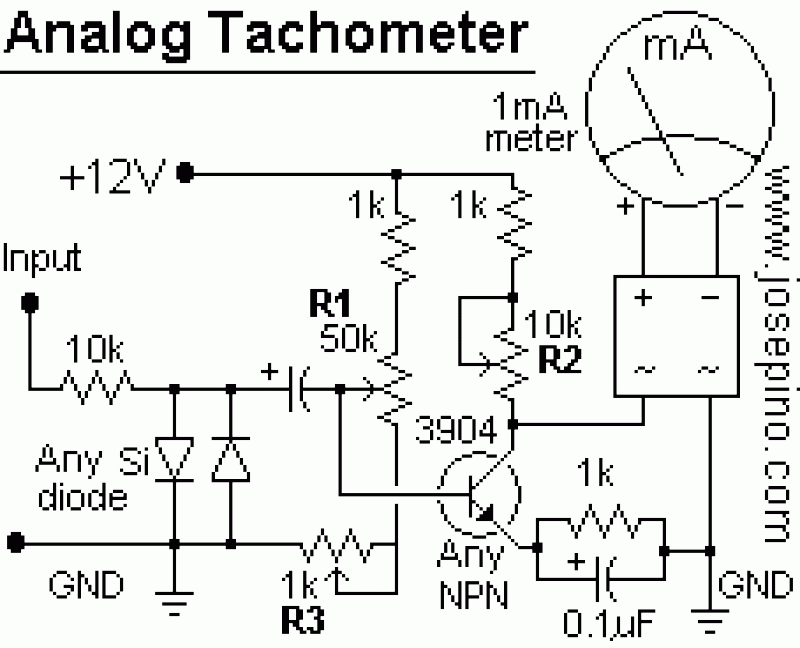
Tachometer
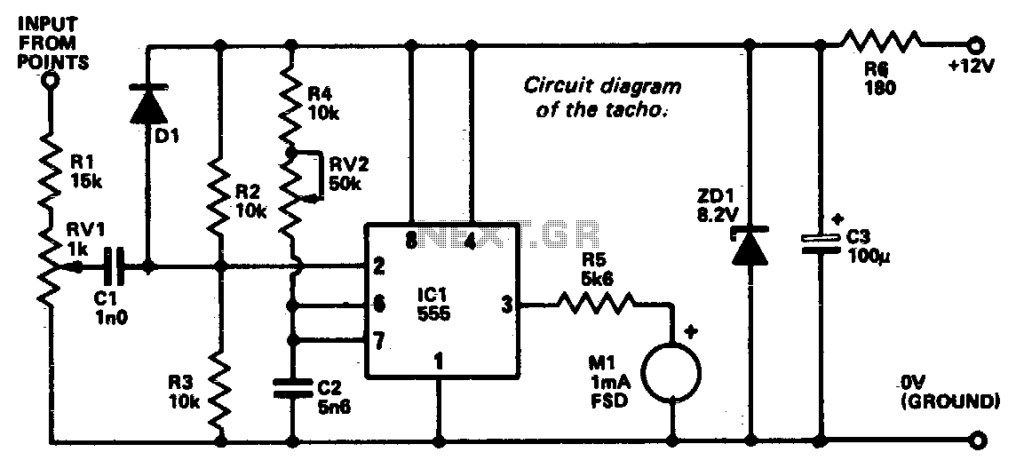
The circuit utilizes a 555 timer IC configured in monostable mode to facilitate the conversion of the electrical signal derived from the low tension side of the distributor into a usable voltage signal that reflects the engine's RPM. In this configuration, the 555 timer generates a single output pulse in response to a triggering event, which is the closure of the breaker points in the ignition system. The timing of this pulse is crucial, as it determines the frequency of the output signal that corresponds to the engine speed.
The components R4 and RV2 form a voltage divider that establishes the duration of the output pulse, which is directly related to the engine speed. The capacitor C2 integrates the signal, smoothing out fluctuations and ensuring that the pulse width remains stable during operation. Resistors R2 and R3 serve a dual purpose; they provide a reference voltage to pin 2 of the 555 timer and ensure that the timer is triggered only when the voltage falls below a specific threshold, which is indicative of the opening of the breaker points.
To enhance the reliability of the circuit, an adjustment potentiometer RV1 is included, allowing the user to fine-tune the input signal level. This adjustment is essential to avoid false triggering, which could occur due to noise or other transient signals present in the electrical system. The Zener diode ZD1, in conjunction with a 180-ohm resistor, acts as a voltage regulator, ensuring that the circuit operates within a stable voltage range despite variations in the input voltage, thus protecting the 555 timer and other components from potential damage due to over-voltage conditions.
Overall, this circuit design effectively translates the mechanical operation of the engine into a measurable electrical signal, providing valuable feedback for monitoring engine performance and facilitating diagnostics.An electrical signal taken from the low tension side of the distributor is converted into a voltage proportional to engine rpm and this voltage is displayed on a meter calibrated accordingly. The 555 timer IC is used as a monostable which, in effect, converts the signal pulse from the breaker points to a single positive pulse the width of which is determined by the value of R4 + RV2 and C2.
Resistors R2 and R3 seta voltage of about 4 volts at pin 2 of ICl. The IC is triggered if this voltage is reduced to less than approximately 2 volts (Ys of supply voltage), and this occurs due to the voltage swing when the breaker points open An adjustment potentiometer RV1 enables the input level to be set to avoid false triggering. Zener diode ZD1 and the 180 ohm resistor stabilize the unit against voltage variations. 🔗 External reference
Related Circuits
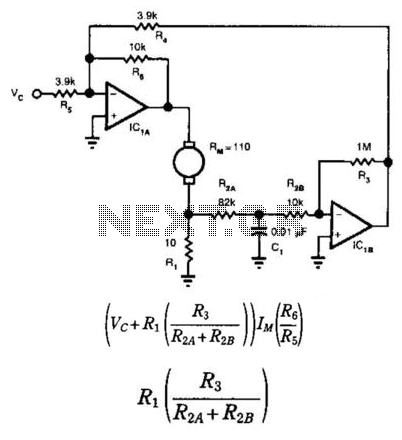
This circuit provides bidirectional speed regulation for small motors and does not require a tachometer. The voltage applied to the motor's windings, which is determined by summing amplifier IC1A, is expressed as a function of the command voltage (Vc)...
The system primarily consists of a permanent magnet disk, an integrated Hall sensor, a strobe gate, time base signal circuits, a power counting circuit, and a digital display circuit. The counting and digital display circuit utilizes the CMOS-LED digital...
The tachometer, also known as a revolution counter, is an instrument that measures the speed of rotating machinery, typically expressed in revolutions per minute (RPM). This project involves creating a custom sensor using a light-emitting diode (LED) as a...
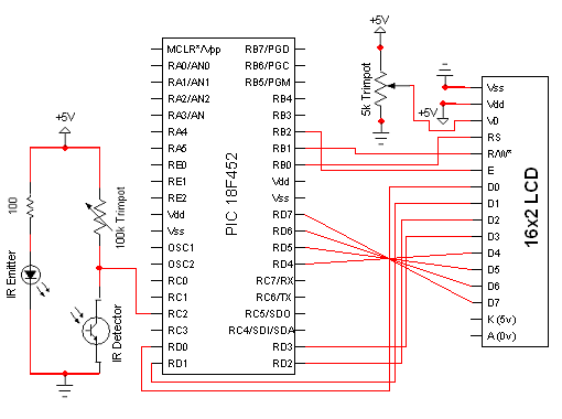
The circuit for the Digital Tachometer/RPM Counter consists of only a few devices. Wire them up according to the following circuit diagram. The PIC used is on a demonstration board, which means the clock, power, and ground pins are...
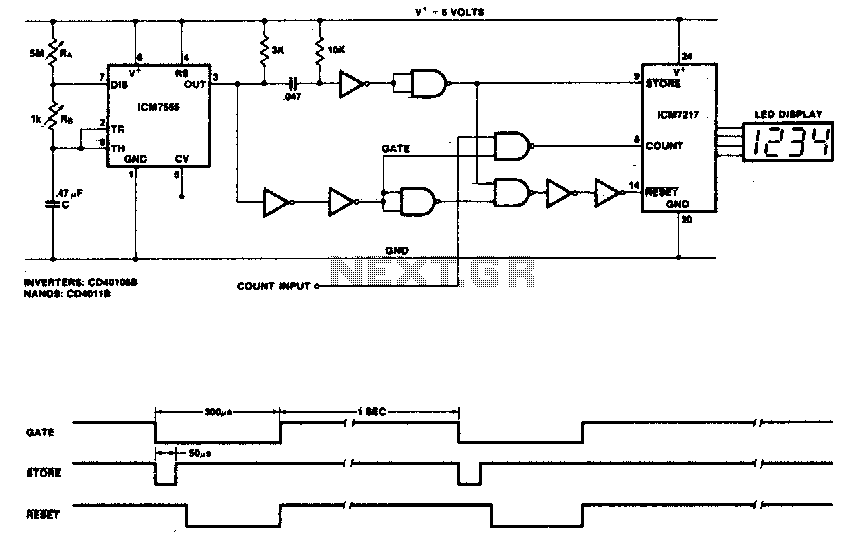
This circuit utilizes the low-power ICM7555 (CMOS 555) to generate the gating, STORE, and RESET signals. The timer is configured as an astable multivibrator to provide the gating signal. Calibration of the system is achieved using a 5 MΩ...
Basically, this is a frequency-current converter. It is used as a frequency meter. Calibrating it can be used as a tachometer. Please be aware this is an experimental project; it wasn't connected to any vehicle, but it should work...