
tate ambient power module

The described circuit setup demonstrates an innovative approach to enhancing power generation through effective grounding and component selection. The dual grounding technique, which involves connecting the circuit ground and antenna ground to separate earth points, is critical for optimizing performance. This method aids in reducing ground loop interference and can improve the overall efficiency of the power collection system.
In terms of component selection, the use of 470uF capacitors allows for increased energy storage and improves the circuit's ability to handle transient loads. The IN60 germanium diodes are particularly advantageous due to their low forward voltage drop, which minimizes power loss and enhances the overall efficiency of the circuit. The decision to replace smaller capacitors with larger values indicates a strategic approach to maximizing the circuit's energy storage capabilities.
The experimental grounding techniques, such as burying aluminum foil sheets, reflect a practical understanding of the importance of grounding in electronic circuits. The larger the surface area of the grounding material, the more effective the grounding becomes, leading to improved circuit performance.
The circuit's ability to achieve 27 volts is notable, especially for a design focused on low-power applications. Although the output is currently utilized for a bright LED, the potential for further enhancements could allow for the powering of more complex devices. This adaptability showcases the circuit's versatility and the engineer's commitment to continual improvement.
Overall, this circuit exemplifies a hands-on approach to electronic design, emphasizing the importance of grounding, component selection, and iterative testing. The results achieved thus far provide a solid foundation for future advancements in power generation and circuit efficiency.Hey another cool thing I found is that if you earth both the earth of the circuit to ground and the other end of the antenna to a separate ground, you increase the power dramaticaly, compared to using a normal antenna and coil. I made a similar coil to the one mentioned on the ambient power web page but it didn`t help. I have tested and found that the power output is greatly related to how large your capacitors are and how well grounded your antenna and circuit grounds are. A metal stake shoved in the ground provides a reasonable ground. But I found that it is much better to get the largest surface area of metal in contact with the ground as possible.
I even tryed digging a hole and planting aluminium foil sheets in the ground. That worked quite well. At the moment I am using the earth of the house for the circuit earth and a metal fence for the antenna earth. This is working great. So far I am using 470uF capacitors and IN60 germanium diodes as they have a low voltage drop and the capacitors collect more current compared to 47uF.
I also replaced the 0. 2uF capacitors in the original diagram to 47uF capacitors aswell. I also intend to replace them all to much higher capacitor values. Although the mentioned 50-500 farred capacitors on the web site cost a fortune as each one costs $1000+ each and I would need 12 of them. The first circuit showen on the web page that had the problem with the diode, I fixed and is running quite well.
I have included a picture of the fixed circuit in this e-mail as an attatchment if you would like to have a look at it. If you have a look at the circuit you will see that it is the diode in red that has been fixed. This circuit has been test run with a computer program as well as practicaly. An example output of current and voltage measurements is also included along with a load (The light bulb).
Unfortunatly practicly I havn`t been able to collect that much current yet. Although I am working on it. But I have been able to get up to 27 volts with this design. At the moment the circuit runs nicely as a night light although it is probably too bright to be used as I night light. I use an 8000 mcd white LED which is definatly bright. But I know that I will inprove the circuit further and will hopefully be able to power more than just an LED.
🔗 External reference
Related Circuits
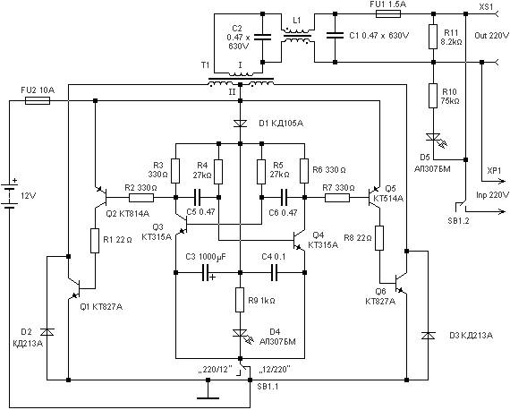
220 watts Uninterruptible Power Supply. Refer to the designated page for an explanation of the related circuit diagram for this power supply. The 220 watts Uninterruptible Power Supply (UPS) is designed to provide reliable backup power during outages, ensuring that...

The input capacitor is used for low-frequency cut-off, with a standard value of 0.1 µF, resulting in a cut-off frequency of approximately 16 Hz. The input capacitor plays a critical role in electronic circuits, particularly in signal processing and audio...
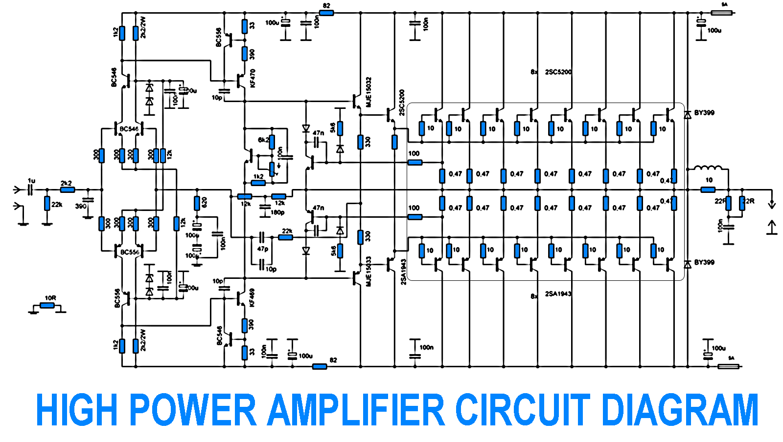
700W Amplifier. Adjusting the amplifier power to 700W appears straightforward, yet it is essential to consider the adjustment of the driving transistors and the frequency offset engagement. It is necessary to modify the current protection circuit that safeguards the...
The distortion produced by a typical solid-state Class-B power amplifier consists of eight mechanisms, all of which may coexist and whose distortion products overlap to create a complex result. Methods for isolating each mechanism for study and minimizing its...
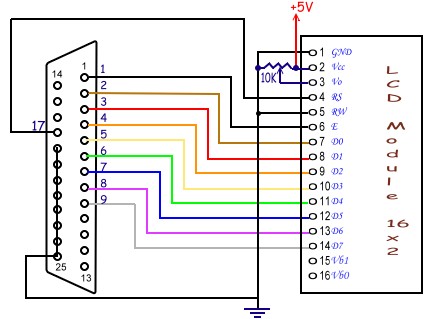
Tutorial on interfacing the 20x4 LCD module to the PC parallel port. The interfacing of a 20x4 LCD module with a PC parallel port involves several steps, which include hardware connections, software setup, and programming. The 20x4 LCD module is...
This lighting solution offers over 90% energy savings compared to incandescent or halogen bulbs, with a lifespan exceeding 50,000 hours. It operates without flickering, making it suitable for human eyes, and produces no RF interference or UV radiation. The...