
transistors Role of capacitor in this circuit

The circuit described involves an oscillator designed to operate at a specific resonant frequency, characterized by the condition that the feedback is in phase with the input signal. This phase alignment is crucial for sustaining oscillations, as it ensures that the output reinforces the input signal. The requirement for the gain to be at least 1 indicates that the system must have sufficient amplification to overcome losses and maintain oscillation.
The mention of the 10µF capacitor suggests its role in coupling or decoupling within the circuit. Proper polarization of electrolytic capacitors is vital, as incorrect polarization can lead to capacitor failure or malfunction. The statement regarding the cathode voltage of 700mV implies that the capacitor must be oriented correctly to handle the expected voltage levels without breakdown.
Furthermore, the current through the 22Ω resistor being approximately 30mA indicates the expected load conditions under normal operation. This current level is significant for determining the power requirements and ensuring that the components used can handle the expected thermal and electrical stresses. The absence of a physical prototype for verification raises questions about the accuracy of these theoretical values, highlighting the importance of simulation or empirical testing in circuit design.
In summary, the oscillator circuit's design hinges on the precise balance of gain, phase alignment, and component specifications, particularly the capacitor's polarization and the current through the resistor. These factors collectively influence the circuit's performance and reliability in generating stable oscillations at the desired frequency.We expect oscillation at the resonant frequency at which the positive feedback is at 0 degrees (in phase) with the input. For oscillation to occur, the gain has to be at least 1 at that frequency. Kaz Oct 30 `12 at 20:39 I still think the 10u cap has wrong polarization. The cathode of the cap can be 700mV at best, that means to polarize the cap correctly, the current in th 22R resistor at average should be 30mA. Didn`t (virtually) build the circuit though to verify, but my feeling says it is wrong. jippie Oct 30 `12 at 21:23 🔗 External reference
Related Circuits

This is a circuit known as a Wien bridge oscillator. The circuit features both positive and negative feedback loops and operates under the control of an operational amplifier (op-amp). The oscillation frequency is determined by the RC time constant,...
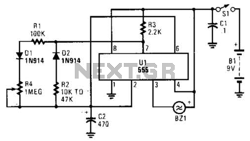
This timer circuit utilizes a 555 IC timer in conjunction with three 74LS193 counters to control an LED display. The circuit is activated by one individual who turns on the piezo buzzer BZ1 through Q1, simultaneously starting the timer....
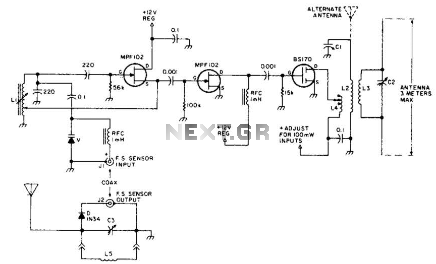
This field strength meter consists of a tuned crystal detector that generates a DC output voltage from a transmitted signal. The DC voltage is utilized to modulate the frequency of a transmitter with a power output of 100 mW,...
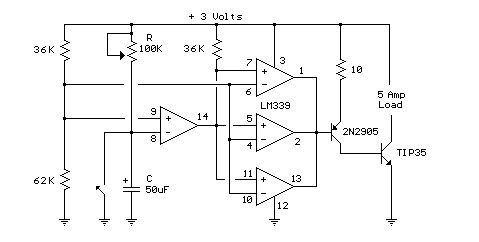
This circuit utilizes an LM339 quad voltage comparator to create a time delay and manage a high current output at low voltage levels. Approximately 5 amps of current can be achieved using two fresh alkaline D batteries. Three of...
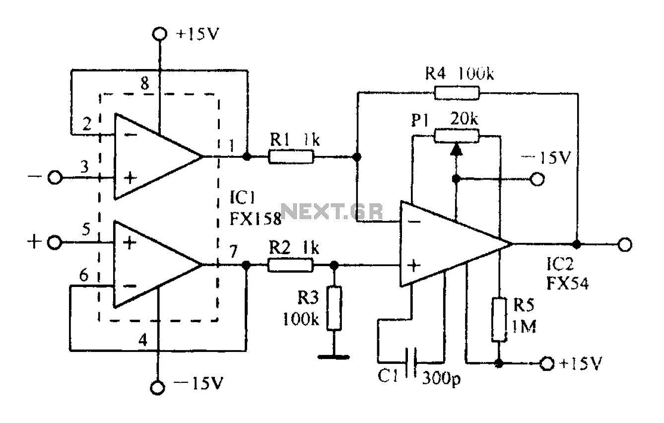
A differential amplifier with input impedance as indicated in the circuit diagram. A differential amplifier is a crucial component in various electronic applications, primarily used to amplify the difference between two input voltages while rejecting any common-mode signals. This characteristic...
The voltage converter can be configured to switch between AC voltage ranges using a selector switch. The measurement circuit is depicted in the accompanying figure. In this configuration, a shunt resistor is placed in parallel with the header, maintaining...