
Telephone Circuits

The circuit design focuses on ensuring minimal interference with the phone line while providing a reliable alert system for users. The use of a battery power source minimizes the risk of affecting the phone line balance, which is crucial for maintaining proper functionality of connected devices. Additionally, the flexibility in audio output allows for customization, catering to various user preferences and situations. The implementation of inverters for generating the ringing signal demonstrates an efficient use of components to achieve the desired functionality without unnecessary complexity. Overall, this circuit serves as a practical solution for managing phone line usage in a household with multiple devices, enhancing user experience while maintaining privacy and control.When a new computer modem enters the household, the demands on the home phone line skyrockets. The Internet surfer can use phone time on a par with the most talkative teenager. And the computer modem user can be quite sensitive about his privacy: simply lifting another receiver can knock him off-line causing emotional stress. The phone wiring maybe modified so that the modem is always in control by connecting the phone line directly to the modem and connecting the rest of the phones to the modem`s "phone" jack. But this solution gives the computer user too much power over the phone line and it doesn`t solve the problem if two computers share a single line.
Here is a simple blinking LED circuit which will alert users when the line is in use before the receiver is lifted. The circuit loads the phone line so lightly that it meets the on-hook telephone equipment leakage specification and the short lamp flashes draw very little current from the nine-volt battery.
One of these devices may be placed at each extension without significantly loading the phone line. The circuit is connected to the red and green wires for a single-line system or the yellow and black wires for the second line in a two-line system. Polarity doesn`t matter, thanks to the full-wave rectifier. In order to preserve your phone line balance, do not power this device from a line-powered power supply.
Only use a battery as shown and insulate the battery and circuitry by building the device into a plastic case. Do not ground the circuitry. The circuit will work with other batteries and battery voltage. Four AA, C, or even D cells (6 volts) will last considerably longer if you have teenagers burning up your batteries.
A small 9-volt rectangular battery will be fine for most users. The diode bridge eliminates polarity concerns. It may be left out but the wires to the phone line may need to be reversed if the circuit doesn`t work properly. The Phone Ringer circuit will work with any ordinary phone including older bell ringer types. The circuit rings the phone in a completely realistic manner until someone answers. When the receiver is lifted the user hears the audio of your choice. It might be another telephone, a tape recording, a favorite talk radio show, a fake busy-signal, a scanner tuned to weather or police, cues for the actor who forgot his next line, or whatever audio source strikes your fancy.
DC current is passed through the phone to activate the phone ’s electronics. Provisions for experimenters include a ring inhibit control and an additional transistor will activate devices when the phone is answered. The ring inhibit control is used to start the ringing when a signal goes low and the activate-on-answer control can start a tape recording or other device when the phone is answered.
For example, the ringer could be triggered by an alarm clock to make an artificial but realistic wake-up call. When you answer, your own voice instructs you about the importance of getting up. This wake-up caller is quite persistent, calling back the instant you hang up! The phone cable will have red and green wires which are simply connected to the points indicated by the schematic.
Polarity should not matter. Other devices may be connected as described but no connection to a "real" phone line is intended. The circuitry is simple and not particularly critical. The first two inverters form a slow pulse generator which controls the ringing rate. Change the 0. 22 uf capacitor to change the ringing rate and change the 22 Meg. resistor in series with the diode to change the length of the ring. The second two inverters generate the 20 Hz ringing signal. This frequency can be changed by changing the. 033uf capacitor. Mechanical bell ringers have a resonant clapper and should be driven with a frequency near 20 Hz but a slight variation may give a better ring. The last two inverters buffer the ringing signal and drive the t 🔗 External reference
Related Circuits
A simple and easy telephone line tester circuit that can be used for testing telephone lines. The telephone line tester circuit is designed to verify the functionality and integrity of telephone lines. It typically comprises a few essential components, including...
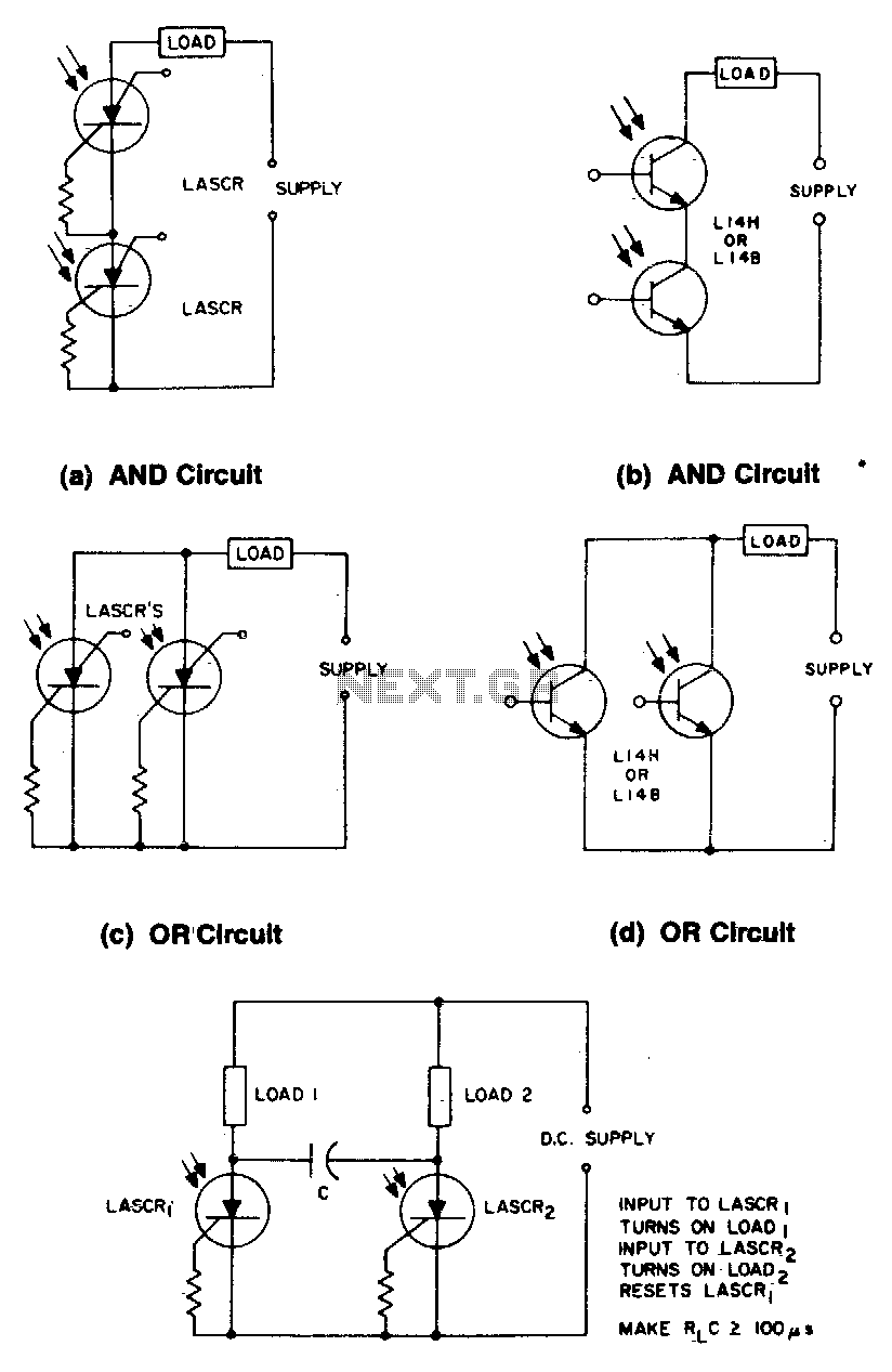
These circuits illustrate some of the common logic functions that can be implemented. The provided circuits serve as examples of fundamental logic functions utilized in digital electronics. Logic functions are the building blocks of digital systems, enabling the execution of...
The Guild "Country Belle" is a distinctive novelty radio designed to resemble an old-fashioned wall telephone. Manufactured in large quantities, this model remains relatively common today. It is identified as model 556, and while prices may vary, it is...
Uploaded with ImageShack.us Uploaded with ImageShack.us Uploaded with ImageShack.us Inquiry regarding experiences with specific circuits. In this context, the inquiry pertains to the performance and functionality of certain electronic circuits that have been shared via an image hosting service. The...
This circuit can manage nine independent telephones using a single telephone line pair, located up to 100 meters apart for making and receiving calls while ensuring conversation privacy. It is particularly useful for multiple members residing in different rooms...
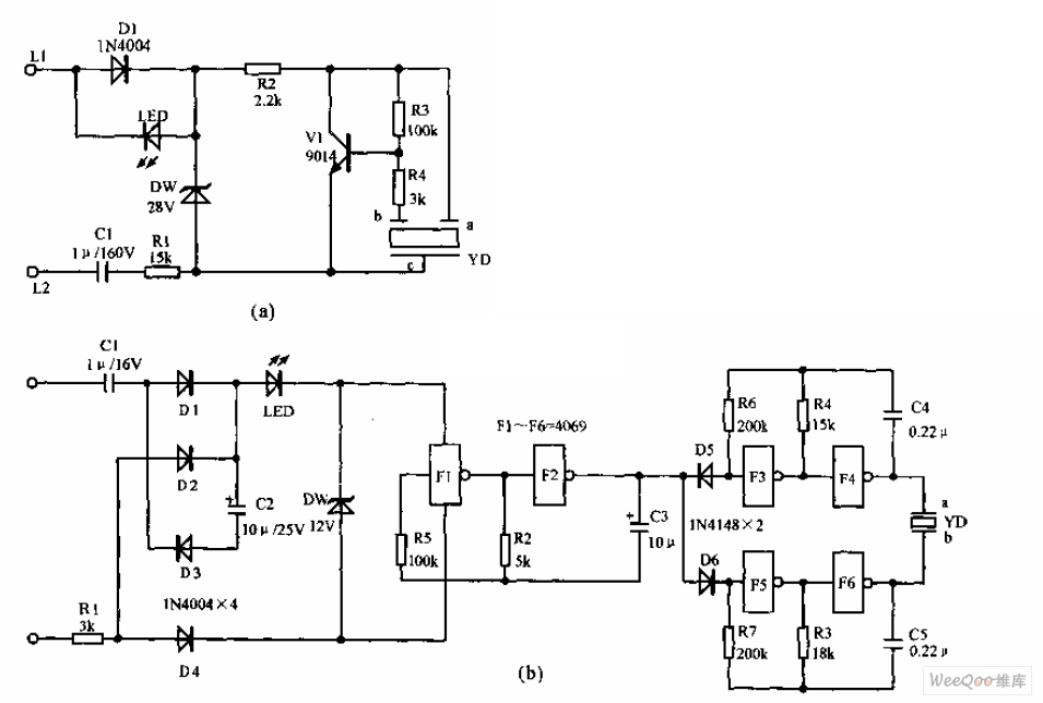
The telephone electronic ringer circuit is illustrated in the provided figure. It features an NPN transistor (either 9014 or 3DG12) as the primary component. The sound device, referred to as YD, functions as both a feedback device and is...