
Telephone line monitors

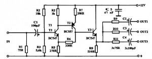
This telephone line monitoring circuit serves as a practical tool for detecting unauthorized connections or faults in an analog telephone system. The core functionality hinges on the use of transistors configured as oscillators, which are sensitive to changes in the line's electrical characteristics. When another device is connected to the line, or if a fault occurs, the circuit's output changes, triggering an audio alert and an LED indicator.
The circuit can be implemented using a basic transistor configuration, where the transistors are arranged in a way that allows them to oscillate when the line is in a normal state. When a fault or an unauthorized connection is detected, the oscillation frequency changes, which can be translated into a sound signal via a small speaker. The LED is connected in such a way that it flashes in response to these changes, providing a visual indication of the line's status.
Powering the circuit directly from the telephone line eliminates the need for an external power source, making it a convenient solution for monitoring telephone line integrity. The design should ensure that the components used can handle the voltage and current levels present in standard telephone lines. Additionally, the circuit should incorporate protection mechanisms to safeguard the components from voltage spikes or other anomalies that may occur on the line.
For implementation, it is crucial to ensure that the polarity of the telephone line is correctly observed, as reversing the connections may lead to malfunction. The circuit can be housed in a compact enclosure, allowing for easy installation and accessibility. Overall, this monitoring circuit provides an effective means of ensuring the security and reliability of telephone communications.If you feel that somebody is tampering with your telephone line you might find this little circuit useful. It detects if there is another telephone connected to the line, if there is a short or an open line. Sound and a flashing light will tell you which is the current situation. The speaker is practically cut out during a normal conversation thus preserving privacy, only the LED will
flash occasionally. The circuit does not require any battery and takes the supply from the telephone line itself. The transistors used are wired in a reversed biased fashion thus behaving as oscillators. You might try the 2N2222A as an alternative (not tested). This monitor is, of course, suitable only for analogue lines. Watch the polarity of the input line: the circuit will not be damaged by a polarity reversal but it will not operate correctly. 🔗 External reference
Related Circuits

This diagram illustrates the schematic of a telephone switcher that utilizes relays. The device interfaces with the telephone line and allows for remote control of up to four relay outputs through a DTMF (dual-tone multi-frequency) telephone. Several user-configurable settings...
A buffered video amplifier is utilized to connect a video player to a receiver or monitor TV over long cable lengths, which may lead to a reduction in signal amplitude and, consequently, a decline in image quality. This amplifier...

The contactless telephone ringer circuit is designed to produce an audible ring and a visual indication when a call is received. Its primary advantage lies in the absence of direct contact between the telephone line and the circuit, which...
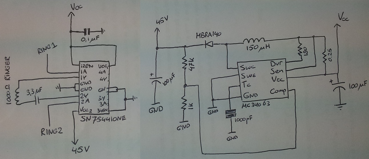
The process involves adapting an old phone for Bluetooth functionality, specifically testing the ringer circuit constructed using schematics from Sparkfun. When connecting a section of the schematic to a 3.5V source (Vcc), an output voltage of 45V is observed,...
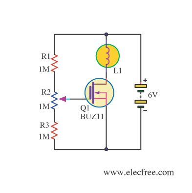
Changing the value of R2 alters the intensity of the lamp in this circuit, demonstrating the utility of a MOSFET as a variable resistor. An N-Channel Power MOSFET, designated as Q1, is utilized in the circuit. The specific part...

An intercom utilizing dual-modular wall jacks is depicted in this circuit. If the wires are accessible in the home telephone cable, this system can be installed with minimal difficulty. The intercom system described employs dual-modular wall jacks, which are standard...