
DTMF Phone Dialer with PIC16F690 and NTE1690

The circuit described integrates a NTE1690 DTMF (Dual Tone Multi-Frequency) dialer chip with a PIC16F690 microcontroller, facilitating functionality within both IP and traditional telephony systems. The design includes two RJ9 ports, allowing for seamless connection between the phone's headset port and the headset itself. This configuration enables the transmission of DTMF tones over the microphone line, making it compatible with various phone types.
Operationally, the device can store up to 12 phone numbers, each associated with a unique bank ID (0-9, SEQ, or RST). The user interface includes a keypad and several functional buttons: ENT (to enter commands), ABT (to abort operations), DEL (to initiate manual dialing), TKO (to change dialing speed), and a green LED indicator to provide feedback during operations.
For number storage, the user presses ENT followed by the designated bank ID, after which the LED illuminates to signal readiness for number input. Numbers can be inputted using the keypad, with specific buttons representing the DTMF symbols for * (SEQ) and # (RST). The DEL and TKO buttons allow for pausing during number entry. Once the number is entered, pressing ENT stores it, while ABT cancels the operation.
Dialing a stored number is straightforward; the user simply presses the corresponding bank ID button. If a number is stored, the device dials it automatically. The copying feature allows users to transfer numbers between banks, enhancing usability. To copy a number, press ABT, select the source bank, then the target bank, with the operation being cancelable at any time.
Manual dialing is initiated by pressing the DEL button, which activates the keypad for direct number entry. The user can exit this mode by pressing DEL again or any of the other functional buttons.
The dial speed can be adjusted based on the user's requirements, with a range from 0 (slowest) to 7 (fastest). The TKO button is used for this adjustment, with the LED indicating the setting process.
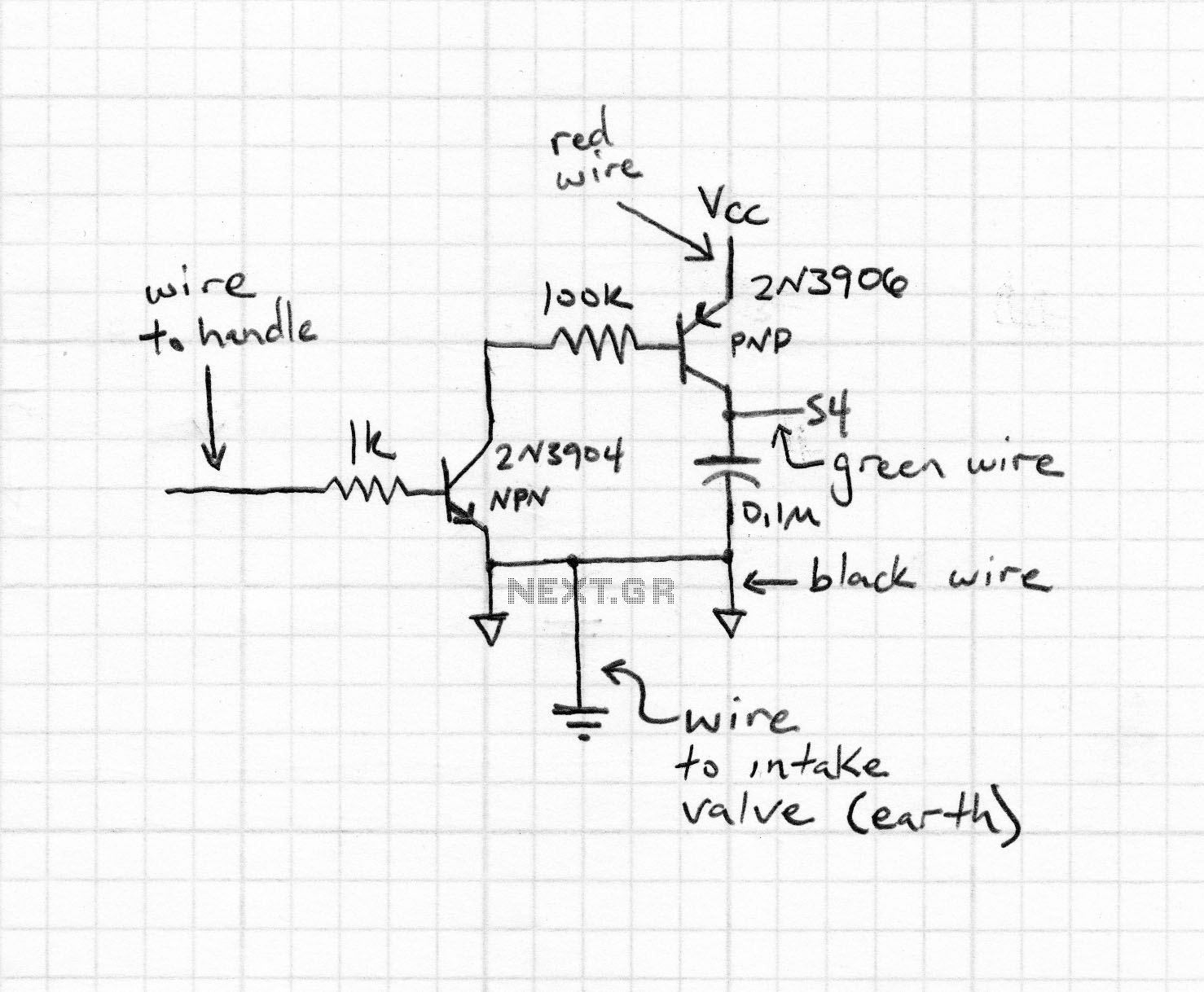
For assembly, it is noted that the specific keyboard layout may vary; adjustments can be made in the software to accommodate different configurations. The power supply is typically provided by a 9V battery regulated by a 7805 voltage stabilizer, although alternative power supply options are viable. The schematic also accommodates variations in handset microphone wiring, offering flexibility in the design's implementation.The circuit uses a NTE1690 DTMF dialer chip and a PIC16F690 microcontroller. Because this is an IP phone and I cannot just send the DTMF tones over the line, the easiest place to plug in the box is between the phone and the handset. The box has two RJ9 ports at the back - one gets connected to the headset's port on the phone, the other to the headset itself.
The dial tones are sent over the microphone line. This way, it works both on IP-phones, and on standard (old fashioned, non-IP) ones. The dialer is operated this way: Storing a number. The device can store up to 12 numbers, identified by a bank ID. The ID is one of the buttons 0-9, SEQ, or RST. To store a number, press ENT, followed by the bank ID button. After pressing the bank ID, the green LED will light up, showing you that the device is expecting the number. Enter the number sequence (up to 15 digits); the SEQ button corresponds to the *-key on a phone; the RST number is #.
You can use the DEL or TKO buttons to insert a pause. When you finish press ENT to store the number, or ABT to discard the changes and leave the old number stored in this bank unchanged. The green LED will turn off at this point. Example: To store the number 555-1234 in bank 0, press ENT-0-5-5-5-1-2-3-4-ENT. Dialing a stored number. Just press one of the 12 bank ID keys (0-9, SEQ, or RST). If there is a number stored in that bank the device will dial the number, otherwise nothing will happen.
Example: To dial the 555-1234 stored number (see "Storing number" above) simply press the 0 button. Copying a stored number from one bank to another. Moving stored numbers around is a useful feature that I have not seen in any off-the-shelf dialer. To copy a number, first press ABT. The LED will light prompting you for source bank ID. Press the source bank button. The LED will remain on, waiting for a target bank ID. Press the target bank button. The number stored in the source bank will be copied to the target bank. You could cancel the operation at any time by pressing ABT. Example: To copy the 555-1234 number stored in bank 0 to bank 3, press ABT-0-3. After this, pressing the 3 button will dial 555-1234. Manually dialing a number. Press the DEL button. The LED will turn on. Now you can use the keypad to dial any number. The SEQ button corresponds to the *-key on a phone; the RST number is #. To exit manual dial mode, press the DEL button again (pressing ENT, TKO, or ABT button will exit manual dial mode too). The LED will turn off at this point. Example: To manually dial 555-9999 press DEL-5-5-5-9-9-9-9-DEL. Changing the dial speed. The maximum reliable dial speed depends on the system that you are dialing into and the noise on the line.
To change the dial speed press TKO. The green LED will light up, indicating that the dialer is waiting for you to select dial speed. Press a number button between 0 and 7. The new dial speed will be set, 0 being the lowest speed, and 7 - the highest. The green LED will turn off after the speed is selected. Example: To switch to the highest dialing speed press TKO-7. Here are some notes, in case you want to build such a dialer: It's not very likely you'll find exactly the same keyboard that I have (this one I got for $0.33 apiece from a great electronics store in Santa Clara, CA; check also my list of SF Bay Area electronic shops). In case your keyboard have different layout, the change is easy to make - simply adjust the K_something constants defined in the beginning of HandheldDialer.asm.
Define your layout by changing the hex digits to match the corresponding button on your keyboard (compare the source and the images of the keyboard to figure out the numbering of the buttons). The schematics doesn't show the power supply. I'm using internal supply with a 9V battery and a 7805 voltage stabilizer. A sample design can be find here. Or maybe you will chose to construct something with external power supply? Handsets may use different microphones, and can be wired in a different way. The schematics diagram shows two ways to connect to the handset cable - use whichever works for you. Special thanks to the friendly guys from the sci.electronics.design newsgroup for the help with the alternative design.
🔗 External reference
Related Circuits
Measurement microphones differ from recording microphones and sound meters; they have a flat response (usually well below 20 Hz and above 20 kHz) and do not have a "weighted" or equalized frequency response. They are optimized for measuring high...
This wireless headphone transmitter ensures a reliable connection over a distance of 2 meters. The oscillator frequency ranges between 1750 KHz and 3500 KHz, utilizing a ferrite bar as the antenna. IC1 amplifies the audio signal, while TC1 serves...
Individuals seeking private listening to their music should incorporate this Headphone Amplifier into the Modular Preamplifier chain. The circuit design prioritizes simplicity while ensuring high-quality performance. This objective is achieved through the use of two NE5532 Op-Amps, where IC1B...
This compact circuit enables automatic recording of phone conversations. It connects to the phone line, the microphone input of a tape recorder, and the remote control jack of the recorder. The circuit detects the voltage on the phone line...
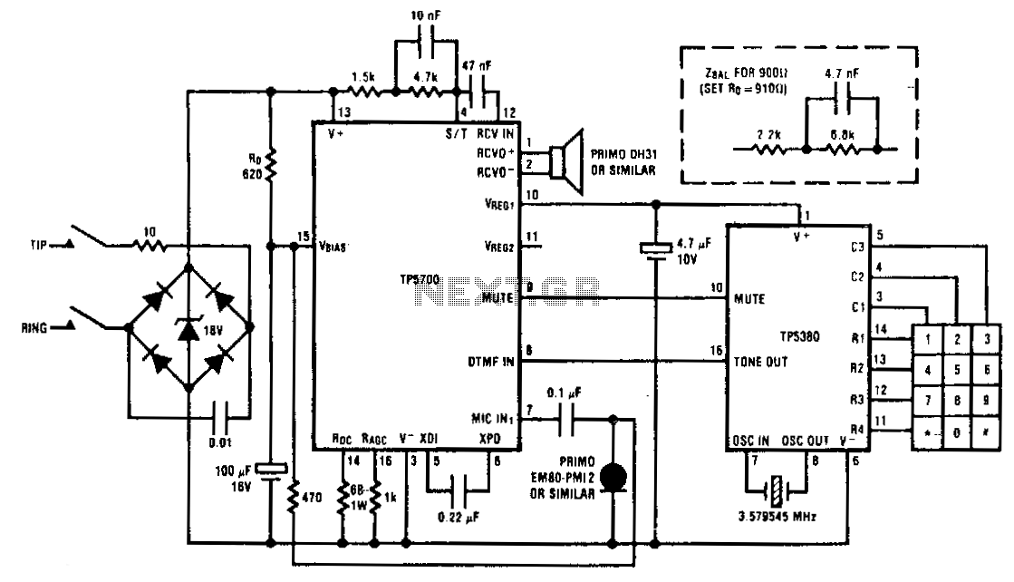
This circuit illustrates the TP5700 interfacing directly with a low-voltage DTMF generator. VREGt provides the required minimum bias of 2 V to enable the TP5380 to detect key closures and pull its mute output high. Subsequently, VREGt switches to...
This indicator shows whether the phone is busy or not. When the line is busy, LED D6 is off. The line voltage at points A and B is attached. By the rectifier bridge behind the connection, the polarity does...