
Tesla Coils Wiring

High-voltage applications, such as those found in Tesla Coils, require careful consideration of wire selection to ensure safety and efficiency. The insulation properties of the wire are critical, particularly in high-voltage scenarios where accidental contact can lead to hazardous situations. Ordinary low-voltage cables can be effectively utilized by maintaining proper spacing and securing the wires to prevent unintentional contact with conductive surfaces. This method not only reduces costs but also leverages air as a natural insulator, which can be particularly advantageous in high-voltage applications.
When selecting cables for high-current applications, it is essential to consider factors such as the material, cross-sectional area, and length of the wire. The resistance of the wire directly impacts the efficiency of the system, as higher resistance leads to greater energy loss in the form of heat. Therefore, using thicker cables for high-current connections is advisable to minimize resistance and ensure optimal performance.
In RF applications, the skin effect must be taken into account, as it significantly influences the effective resistance of conductors at higher frequencies. The utilization of materials such as copper sheets for RF ground connections can enhance efficiency and reduce material waste, providing a more effective solution than traditional round conductors. Overall, careful consideration of cable selection, insulation, and conductor properties is vital for the reliable operation of high-voltage and high-current electronic circuits.Because of the high voltages found in a Charge & Primary sections it seems natural to look for cable with high voltage ratings, such as neon sign cable, medical X-ray equipment cable & car engine spark plug leads. The first two would be fine for connecting the NST to the spark gap but the spark plug leads are useless (too high a resistance).
Howev er, you don`t need to spend lots of money on fancy HV cable because all sorts of ordinary wire would work too. All you need to do is think about insulation. For a circuit to work you need wires to conduct the electricity between the components. A bare piece of wire will do this perfectly but you now have the problem of wires accidentally touching and shorting out.
Depending on the voltage being used you may also have the added risk of electrocution! Insulation is used to solve both these problems but for high voltages, like in a Tesla Coil, the cost of suitably insulated cable is high. The solution is to use ordinary low voltage cable, or bare wire, and use air as your insulatior (just like the big boys do with the National Power Grid!).
All you need to do is to secure the wires in such a way that they cannot short against anything conductive and are at a safe distance from operator`s hands. All conductors, except for `superconductors`, resist the flow of current through them. The value of this resistance is determined by the material used for the conductor and by its size. As the cross-sectional area `a` gets smaller, or the length of the wire `l` gets longer, the resistance `R` increases.
The higher the resistance the more electrical energy is used just in fighting against it. This causes power to be lost in the form of heat. Example: The heating element in an electric kettle uses wire with a high resistance to generate heat. The wire connecting the kettle to the wall socket has a very low resistance, to avoid heating. High current connections in the `Primary` section require thick cables to keep resistance values to a minimum.
Cables `C`, `D` and `E` can be used for high current Tesla Coil use but should be treated as single conductors (see below). Cable `F` is good for high currents too but not as easy to find in the shops. The low current `Charge` section can use thin cable without any measurable loss of power. Cables `A` and `B` are fine. By removing the outermost layer of insulation from cables `C`, `D` and `E` the individual wires are perfect too (see below).
Skin effect is the term used to describe current flower primarily in the outer layer, or skin, of a conductor. The skin depth gives the thickness of conductor in which most of the total current flows. The above cross-section pictures show that as frequency increases the centre of the conductor becomes less and less used for current flow.
In practice this means that although your big fat cable may have a low resistance to DC current flow, at RF frequencies the resistance increases considerably. Note how the metal at the centre of the wire is not used and is therefore wasted expense. For my RF ground cable I cut up a roll of copper sheet to make a 2 inch wide by 6 thou strip. If this amount of copper had been a round conductor, there would have been wasted metal at its centre.
🔗 External reference
Related Circuits
The electrical wiring diagram for the 1993 VW Passat includes the Engine Control Module, Automatic Control Unit, and Automatic Solenoid. This diagram illustrates the connections and wiring between various components of the vehicle's system, such as the multi-function switch,...
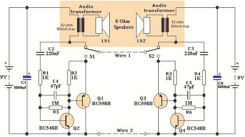
Wiring 2-Wire Intercom. According to Wikipedia, an intercom is a stand-alone electronic communications system intended for limited or private dialogue. A 2-wire intercom system is designed to facilitate communication over a limited distance, typically within buildings or residential areas. The...

The circuit utilizes six 12-volt lead-acid batteries to power the load. Three batteries are connected in series to generate 36 volts, while the other three are connected in parallel to maintain 12 volts. The total discharge current is 30...
The American Electrician describes a glass battery jar measuring six inches by eight inches, wound with 60 to 80 turns of American wire gauge No. 18 B & S magnet wire. Inside this jar is a primary winding consisting...
"Cold electricity" refers to RF frequency alternating current (AC). In sinusoidal AC, the voltage is positive for half the cycle and negative for the other half. An oscilloscope can display this waveform, but a voltmeter may read zero because...
Two schematic diagrams illustrate a series and a parallel circuit configuration that Tesla may have utilized. The components featured are the 70L7GT Half Wave Rectifier tubes, which are surprisingly still available today. While there is an interest in accessing...