
The clock circuit diagram for racing

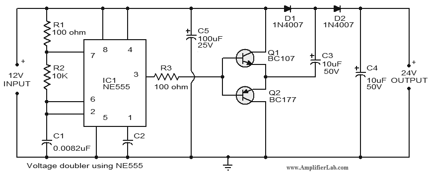
The described clock circuit leverages the 555 timer, which is renowned for its versatility in timing applications. The 555 timer can operate in several configurations: monostable, bistable, and astable, each serving different timing and pulse generation needs. In this specific application, the clock is likely configured in the astable mode to continuously generate a square wave output, which can be utilized to drive a display or provide timing signals.
The selection of the CD555 timer ensures compatibility with both TTL and CMOS logic levels, allowing for integration into various digital systems. The use of a 3DG6 transistor serves as a switching element, enabling the control of higher power loads that may be connected to the clock circuit. The choice of 5mm diodes (VD1 to VD3) suggests the need for protection against reverse polarity or to manage current flow within the circuit, ensuring reliable operation.
Incorporating an analog quartz oscillator enhances the precision of the clock, providing a stable frequency reference. This is crucial for applications requiring accurate timing, such as in competitions where precise timekeeping is essential. Overall, the design emphasizes simplicity and reliability, making it suitable for educational purposes, hobby projects, or competitive events where timing accuracy is paramount. The minimal component count not only simplifies the assembly process but also reduces potential points of failure, contributing to the circuit's robust performance.The chart shows the clock for the competition, which is assembled with 555 circuit, with the features of novel circuit, reliable performance, easy making, intuitive interesting. 555 circuit has two categories of bipolar circuit (TTL) and complementary metal oxide semiconductor-type (CMOS) integrated circuit.
It is a very broad application IC with only a small amount of external components, it is very easy to form a single stable, bistable, non-stable circuit. The selection of components: IC uses bipolar CD555 time base circuit. VT selects 3DG6 transistor. VD1 ~ VD3 chooses 5mm. The clock uses analog quartz. 🔗 External reference
Related Circuits
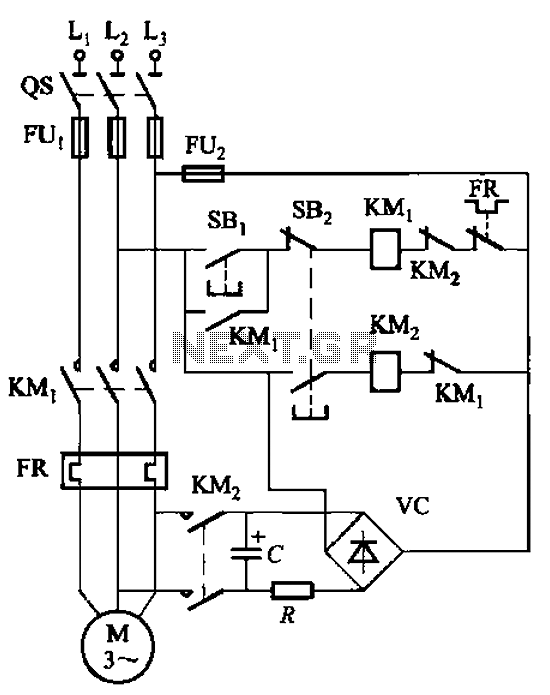
The circuit depicted in Figure 3-138 utilizes the principle of energy storage through capacitor discharge to achieve braking. The capacitance (C) and resistance (R) parameters are determined based on the size of the motor power. The capacitance (C) is...
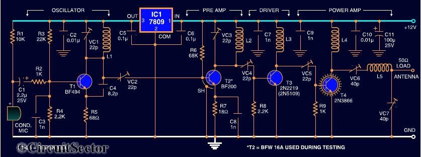
Here is the circuit diagram of a four RF stage FM transmitter. The stages include a very high frequency (VHF) oscillator built around the HF transistor BF494, a pre-amplifier using the BF200 transistor, a driver transistor 2N2219, and a...
The automatic sprinkler controller circuit consists of a +12 V power supply circuit, a light control circuit, and an irrigation control circuit, as illustrated in the accompanying figure. The +12 V power supply circuit includes a knife switch (Q),...
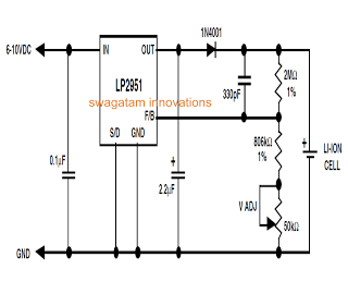
Unlike lead-acid batteries, one advantage of lithium-ion (Li-Ion) batteries is that they can be charged at a 1C rate initially. This means the charging current can be as high as the rated ampere-hour (AH) capacity of the battery at...
Project Manager Jim Heck, G3WGM, has provided an exclusive audio interview to Bob McCreadie, G0FGX, from TX Factor, detailing the tests and potential issues involved. Membership in AMSAT-UK is available to anyone interested in amateur radio satellites or space...
The circuit consists of inverter and charger sections. The inverter section utilizes the NE555 timer, while the charger section is based on the LM317 adjustable regulator. In the inverter section, the NE555 is configured as an astable multivibrator, generating...