
The counter

The device's circuit design incorporates several key components and features that enhance its functionality and reliability. The input circuit is crucial as it not only filters incoming signals but also serves as a protective barrier against voltage spikes, ensuring the integrity of the subsequent circuitry. The choice of four transistors in the one-shot section allows for effective pulse generation, providing precise timing control for the counter. The 470nF capacitor is critical in determining the pulse duration, while the 8F polarized capacitor ensures that the one-shot mechanism is adequately timed to avoid erroneous multiple counts.
Power management is an essential aspect of this design. The use of a 6LR61 9V battery is advantageous due to its longevity, especially given the low power consumption of the circuit under normal conditions. The test button feature is a practical addition, allowing users to verify the operational status of the unit easily. The incrementing counter response provides immediate feedback, which is particularly useful for maintenance checks.
The integration of optocouplers facilitates the safe interfacing of different voltage levels between the one-shot circuit and the counter, preventing potential damage from voltage mismatches. This design choice enhances versatility, allowing the use of various counter types, including digital and mechanical, provided the necessary interface adjustments are made.
The digital 5-digit LCD counter is a suitable choice for this application, balancing power consumption with functionality. The inclusion of a reset switch and piezo speaker enhances user interaction, providing audible confirmation of operations.
In terms of component selection, the recommendation for 1% precision parts in the input circuit underscores the importance of accuracy in signal processing. The use of high-voltage capacitors and power resistors necessitates careful insulation to ensure safety and reliability. Overall, this circuit design exemplifies a well-thought-out approach to creating a robust and efficient counting mechanism, suitable for various applications.The circuit of this device is quite simple: an input circuit filters the signal provided by the antenna to reduce sensibility to other phenomena and protects against over voltages. The four transistors realize a "one-shot" section that is triggered by the input circuit and provides pulses of about 0.
05 seconds to the counter (the 470nF capacitor s ets this time). When the one-shot is triggered it cannot be retriggered for about one second (imposed by the 8 F polarized capacitor) to avoid multiple counts for the same strike. This part is powered by a 6LR61 9V cell and, since the power consumption is lower than 1 A (when no strikes are detected) a single cell will last for some years.
The test button allows to check if the battery is still operational: each time it`s pressed the counter should increment and, if hold down, the counter should increment about once per second. The two optocouplers interface the output of the one-shot circuit with the real counter and with the PC.
I used a digital 5-digits LCD counter powered by a single LR6 (AA) 1. 5V cell. The power consumption of this counter is about 1. 5 A and the battery life is about one year. This counter also has a reset switch and a piezo speaker that beeps on every operation. Any other counter should work fine (even mechanical ones) but the interface must be modified. The insulation between the counter and the one-shot provided by the optocoupler here is not necessary: I just used an optocoupler to adapt the two different supply voltages (9V and 1. 5V). A transistor and a resistor could work as well. A 6-9V DC counter can be directly connected between the collector of the 2N2904 ant the ground. This circuit is not critical and every semiconductor can be replaced with similar ones. The input circuit uses power resistors and high voltage capacitors: it must be well insulated. For better accuracy the input circuit should use 1% precision parts. 🔗 External reference
Related Circuits
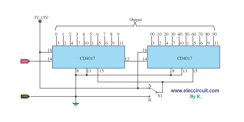
When designing a counter circuit that counts from 0 to 99, an effective approach is to utilize the IC LM4017, which is a decade counter. The LM4017 is a CMOS decade counter capable of counting from 0 to 9, and...

The circuit for the Digital Tachometer/RPM Counter consists of a few components. They should be connected according to the provided circuit diagram. The PIC used is on a demonstration board, meaning the clock, power, and ground pins are already...
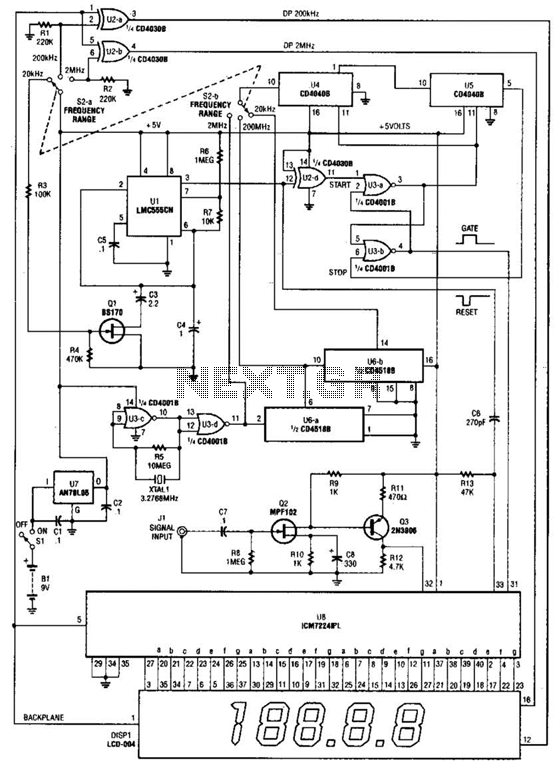
This is a schematic and block diagram of a 2-MHz frequency counter. It utilizes an LSI counter/display driver, an LCD readout, and several logic chips for timebase and timing pulse circuitry. Q2 and Q3 serve as a signal (input)...
This is an image Schematic. No Description available. The provided input indicates that there is an image schematic without any accompanying descriptive details. In the absence of specific schematics or circuit details, it is essential to consider the typical...
This circuit symmetrically divides an input by virtually any odd number. The circuit contains n+l/2 clocks twice to achieve the desired divisor. By selecting the proper n, which is the decoded output of the 74LS161 counter, divisors from 3...

This circuit utilizes two J-K flip-flops to create a three-bit binary counter, deviating from the conventional method of employing three flip-flops—one for each binary bit. In this design, the clock pulse from a 555 timer output serves as a...