
3-Bit Binary counter

This circuit design represents an innovative approach to binary counting using J-K flip-flops while minimizing component count. The two J-K flip-flops in conjunction with the 555 timer create a functional down counter that effectively demonstrates the principles of digital electronics. The use of the 555 timer as a clock source is particularly advantageous due to its reliability and ease of implementation.
In practical applications, the circuit can be used in various digital devices where binary counting is required, such as in digital clocks, timers, or event counters. The design's simplicity allows for easy modifications, enabling the addition of features like reset functionality or the ability to switch between up and down counting modes with minimal effort.
The careful construction and testing approach outlined in the description is crucial for ensuring the successful operation of the circuit. By validating each component's functionality before integration, one can isolate and address potential issues early in the development process. This strategy not only enhances learning but also fosters a deeper understanding of circuit behavior and troubleshooting techniques.
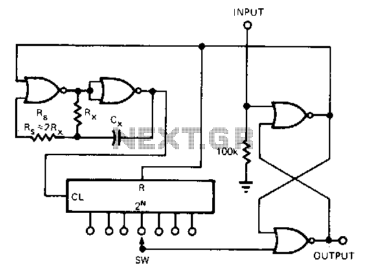
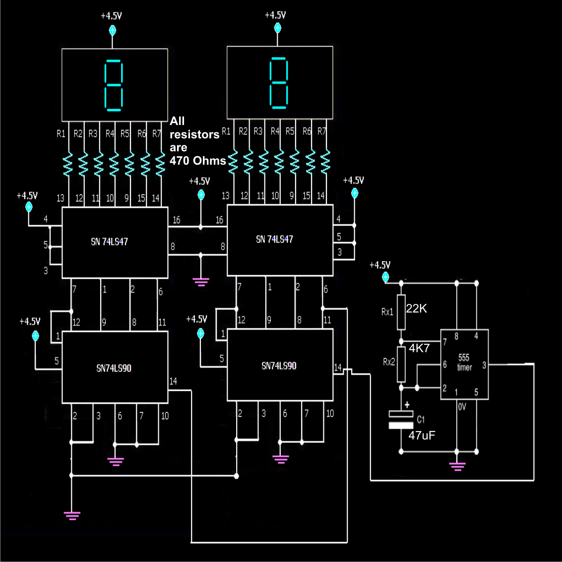
Overall, this circuit serves as an excellent educational tool, providing insights into the operation of flip-flops, timer circuits, and binary counting mechanisms, while also emphasizing the importance of systematic construction and testing in electronics projects.This circuit "cheats" by using only two J-K flip-flops to make a three-bit binary counter. Ordinarily, three flip-flops would be used - one for each binary bit - but in this case we can use the clock pulse (555 timer output) as a bit of its own. When you build this circuit, you will find that it is a "down" counter. That is, its count sequence goes from 111 to 110 to 101 to 100 to 011 to 010 to 001 to 000 and then back to 111. While it is possible to construct an "up" counter using J-K flip-flops, this would require additional components and introduce more complexity into the circuit. The 555 timer operates as a slow, square-wave oscillator with a duty cycle of approximately 50 percent.
This duty cycle is made possible by the use of a diode to "bypass" the lower resistor during the capacitor`s charging cycle, so that the charging time constant is only RC and not 2RC as it would be without the diode in place. It is highly recommended, in this experiment as in all experiments, to build the circuit in stages: identify portions of the circuit with specific functions, and build those portions one at a time, testing each one and verifying its performance before building the next.
A very common mistake of new electronics students is to build an entire circuit at once without testing sections of it during the construction process, and then be faced with the possibility of several problems simultaneously when it comes time to finally apply power to it. Remember that a small amount of extra attention paid to detail near the beginning of a project is worth an enormous amount of troubleshooting work near the end!
Students who make the mistake of not testing circuit portions before attempting to operate the entire circuit often (falsely) think that the time it would take to test those sections is not worth it, and then spend days trying to figure out what the problem(s) might be with their experiment. Following this philosophy, build the 555 timer circuit first, before even plugging the 4027 IC into the breadboard.
Connect the 555`s output (pin #3) to the "Least Significant Bit" (LSB) LED, so that you have visual indication of its status. Make sure that the output oscillates in a slow, square-wave pattern (LED is "lit" for about as long as it is "off" in a cycle), and that it is a reliable signal (no erratic behavior, no unexplained pauses).
If the 555 timer is not working properly, neither will the rest of the counter circuit! Once the timer circuit has been proven good, proceed to plug the 4027 IC into the breadboard and complete the rest of the necessary connections between it, the 555 timer circuit, and the LED assembly. 🔗 External reference
Related Circuits
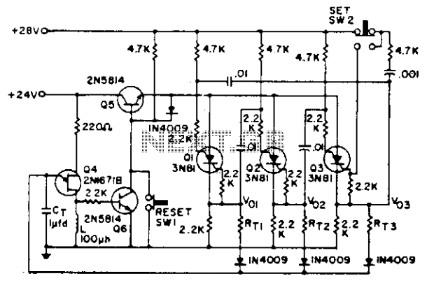
Shift pulses are generated by the unijunction transistors. The intervals between pulses are controlled by CT and RT. A different RT can be selected for each stage of the counter as shown. The circuit utilizes unijunction transistors (UJTs) to generate...
This simple counter can be used to count pulses, serving as the basis for a customer counter, similar to those found at the entrances of some stores, or for any other application requiring counting. The described simple counter circuit is...
This CMOS circuit functions as a one-shot time delay switch and a general-purpose timer. It comprises a gated oscillator and a latch utilizing a CD4001 quad 2-input NOR gate, along with a CD4020 14-stage counter. The timing interval, TON,...
To ensure the circuit functions properly, it is crucial to correctly configure the fuse bits within the AVR microcontroller. These fuse bits can be set using the programmer employed to upload the software. For those interested in the technical...
A simple frequency counter circuit can be easily constructed by any electronics enthusiast for its intended purpose. The circuit diagram was provided by Mr. Kapital through an order on Fiverr. The functioning of the circuit involves generating positive voltage...
The circuit employs an astable multivibrator to alternate between heads and tails conditions, while a flip-flop is utilized to retain the state determined by the multivibrator. As a result, the circuit is designed so that the flip-flop's state changes...