
The English Ringing Converter Technical Description

When the converter detects a ringing signal on the line, it disconnects the phone from the line and switches it over to the internal ringing supply. The device generates a 25Hz ringing voltage by applying 24 volts to a split bobbin transformer in reverse to produce the high-voltage ringing. Upon answering the phone, the converter detects the loop current, disconnects the phone from the ringing supply, and reconnects it to the network. If the phone is used to initiate a call, the converter remains passive, as the phone is normally connected to the network.
The first task is to detect incoming ringing from the network, which in the US is characterized by 108VAC at 20Hz with a cadence of 2 seconds on and 4 seconds off. This detection is accomplished using a 47μF 250V capacitor, a 2200-ohm resistor, and an optocoupler. Additional zener diodes are employed to prevent false triggering of the ringing detector for voltages below approximately 35VAC. This circuit also provides a Ringer Equivalence Number (REN) of 1.
The next requirement is to detect an off-hook condition on the telephone. This is achieved with a loop current detector, which consists of an 82-ohm resistor and an optocoupler. The resistor and optocoupler exhibit about a 1.5V forward drop when loop current flows, while presenting negligible AC impedance. This characteristic is critical as telephone lines often carry significant common mode noise (primarily 60Hz and AM radio signals). By imposing minimal AC load, the detector does not unbalance the line, thus preventing hum in the phone.
Control of the entire system was a significant challenge. Initially, the control block remained unimplemented on the schematic for an extended period. The two options considered were a small FPGA or a programmable microcontroller. Ultimately, an Atmel 89C2051 microcontroller was selected due to familiarity with the 8051 architecture, allowing for straightforward code development. The resulting code size was unexpectedly large, nearly 1K, for such a simple function.
Two input signals are directed to the microprocessor, which manages both a ringing relay and the drivers for the ringing generator. The Atmel 89C2051 was chosen for its suitability, as its 24-pin configuration met the design requirements. Operating in power-down mode when inactive, the microprocessor typically consumes less than 1mA. The processor runs at a reduced clock speed of 6.144 MHz, yielding a cycle time of 2.048μs. A light-emitting diode (LED) connected to one of the processor's I/O ports facilitates debugging by indicating the state of the finite state machine. This feature proved invaluable during development, allowing for real-time monitoring of the code's state transitions with an oscilloscope.
To generate the English ringing signal, the phone is disconnected from the network via the relay and connected to the internal ringing supply. The relay is designed such that, in its default unpowered state, the phone remains connected to the network. The ringing supply consists of a split bobbin transformer configured in reverse and powered accordingly.This device can`t be legally hooked up to the PSTN as there is all sorts of red tape you need to go through to get the device registered for that. The basic functional blocks of the English ringing converter are pretty simple. It has a ringing detector, a loop detector, a ringing generator, a power supply, and a microprocessor for control.
American ringing is a 2 second on, 4 second off ringing voltage at 20Hz. English ringing is 400ms on, 200ms off, 400ms on, and 2 seconds off ( a double ring ). It is also at 25Hz and and a slightly lower voltage ( 80VAC vs 108VAC ). When the converter detects ringing on the line, it disconnects Rosemary`s phone from the line and switches the telephone over to the internal ringing supply. It then generates 25Hz ringing voltage by driving 24 volts into a split bobbin transformer backwards to generate the high voltage ringing.
When Rosemary answers her phone, the converter detects the loop current and disconnects the phone from the ringing supply and connects it back up to the network. In the case of Rosemary initiating a call, no action is required on the part of the converter, as the phone is normally connected up to the network by default.
The first thing you need to do is detect inbound ringing from the network. In the US, this is 108VAC at 20Hz with a cadence of 2 seconds on and 4 seconds off. This is done with a. 47uF 250V capacitor, a 2200 ohm resistor, and an optocoupler. The extra zener diodes prevent false tripping of the ringing detector for anything less than about 35VAC. This circuit also provides a REN of 1. 0. The next thing you need to detect is an off-hook condition on the phone. This is done with a loop current detector that consists of an 82 ohm resistor and optocoupler. The resistor and optocoupler have about a 1. 5V forward drop when loop current is flowing, but have no AC impedance. This is important because telephone lines have lots of common mode noise on them ( mostly 60Hz and AM radio components ).
Since it presents almost no AC load, the detector doesn`t unbalance the line and cause hum in the phone. The biggest problem I had was how to control the whole thing. The control block sat for a year or so as an empty block on the schematic. The two choices were to either do a small FPGA or use a programmable microcontroller. The logic was very simple, but in the end I decided to go with an Atmel 89C2051 microcontroller. I`ve done a lot of work with the 8051 architecture in the past, and it was fairly simple to write the code for this.
I was quite surprised that the code turned out to be almost 1K in size for such a simple function. The two input signals are fed into the microprocessor. The microprocessor controls both a ringing relay and the drivers for driving the ringing generator. I picked an Atmel 89C2051 for the job because I`m comfortable with the 8031 architecture, and the 24-pin device was perfect for what I needed. Using the power down mode when not busy, the processor typically draws less than 1mA during operation.
I also run the processor at a slightly slower 6. 144 MHz speed that gives 2. 048uS per processor cycle. I included a LED wired to one of the processor I/O ports for debugging purposes. It turned out to be real useful. I wrote the code to pulse out what state it was in in the finite state machine. I then hooked up a scope to the LED and could monitor what states the code went to for different inputs. It only took three revisions of the code to get the bugs out. When we want to ring Rosemary`s phone in the English way, we disconnect the phone from the network with the relay and connect it to our ringing supply.
The relay is wired so that in the default unpowered state, the phone is connected to the network. Our ringing supply is just a split bobbin transformer wired backward and fed from the 🔗 External reference
Related Circuits
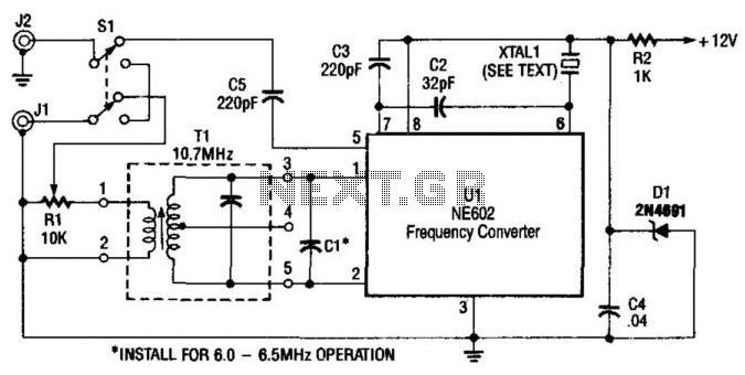
A Signetics NE602 is utilized in this converter to tune the frequency range of 9.5 to 9.8 MHz. An AM car radio functions as a tunable intermediate frequency (IF) amplifier, with the output being taken from J2, the auto...
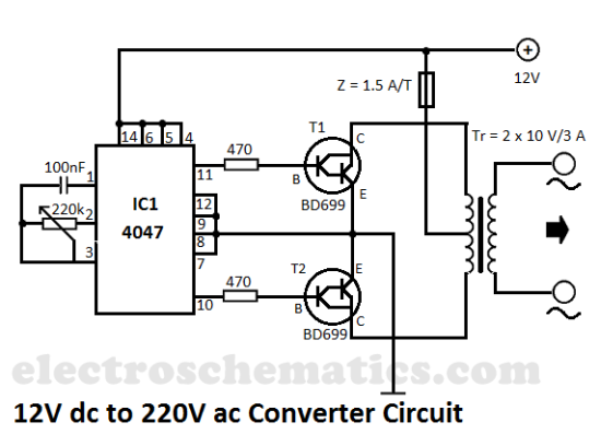
This DIY 12V to 220V voltage converter is built with a CMOS 4047, which serves as the main component for transforming 12V DC into 220V AC. The 4047 operates as an astable multivibrator, generating a symmetrical rectangular signal at...
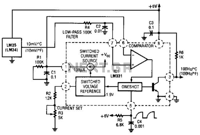
In this circuit, an LM34 or LM35 generates a frequency that is proportional to temperature. The reference current (138) is established through resistor R3. The output can be utilized to drive a display, frequency counter, or other indicating devices...
Switching regulator subsystems intended for use as DC to DC converters. 3V to 40 Volt DC Converter circuit. The use of switching regulators is becoming more pronounced than that of linear regulators because the size reductions in new equipment...
This is a 35.3 to 10.7 MHz converter circuit. It converts the 35.3 MHz signal coming from a VHF/UHF tuner down to an FM tuner to decode the TV audio in FM. The 35.3 to 10.7 MHz converter circuit is...
This high voltage converter circuit begins with a 30-volt power supply and is capable of delivering output voltages ranging from 0 to 3 kV for version 1, or from 0 to 10 kV for version 2. The high voltage converter...