
Propeller Clock Mechanically Scanned LED Clock

The described circuit involves a motor-driven propeller that creates an optical illusion by utilizing a microprocessor to control a series of seven LEDs. The microprocessor is programmed to manage the timing and sequence of the LED patterns in synchronization with the rotational speed of the propeller. This setup effectively simulates a larger array of LEDs, specifically a 7 by 30 grid, despite the limited number of actual LED components used.
The motor is typically a DC or stepper motor, selected based on the required speed and torque to achieve the desired visual effect. The propeller is attached to the motor shaft and spins at a predetermined rate, which can be adjusted via a PWM (Pulse Width Modulation) signal from the microprocessor to control the motor speed.
The microprocessor, which could be an Arduino, PIC, or similar, is responsible for generating the timing signals that dictate when each LED should turn on or off. The timing must be precise, as it directly influences the illusion of a continuous display. The microprocessor can be programmed with algorithms that account for the rotational speed of the propeller and the persistence of vision effect, allowing the LEDs to appear as if they are part of a larger display.
The seven LEDs are connected to the microprocessor through current-limiting resistors to prevent damage from excess current. The circuit may also include a power supply, typically a battery or an external power source, to provide the necessary voltage and current for both the motor and the microprocessor.
In summary, the circuit combines mechanical motion with electronic control to create a visually appealing effect, demonstrating the principles of persistence of vision and the effective use of microcontrollers in interactive display technologies.A motor spins the "propeller", and a small microprocessor keeps track of time and changes the pattern on seven LEDs with exact timing to simulate a 7 by 30 array of LEDs. It is an illusion, but it works nicely. 🔗 External reference
Related Circuits
This circuit is designed for use in a basketball shot clock. To initiate the 24-second countdown, both the 24s LOAD switch and the Reset switch must be pressed simultaneously. If this condition is not met, the countdown will begin...
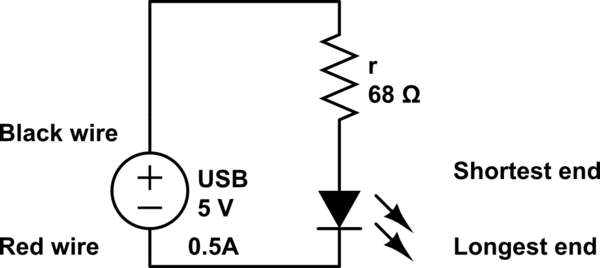
The LED operates at 3V, and based on information available online, a blue LED typically supports a maximum current of 0.03A. Given the available current from the USB source, the intention is to construct a parallel circuit. However, the...
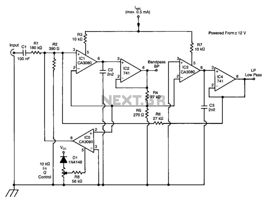
A standard dual integrator filter can be constructed using a few CA3080 operational amplifiers. By varying the parameters L, A, B, and C, the resonant frequency can be swept over a range of 1000:1. At IC1, three current-controlled integrators...
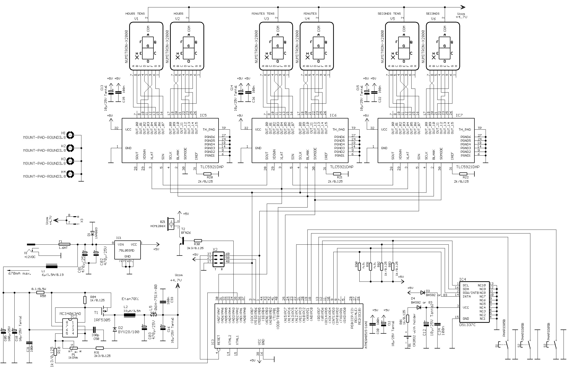
Numitrons are display devices similar to Nixie tubes, specifically designed for low voltage applications. They function as incandescent displays, utilizing filaments for the segments. A typical seven-segment readout comprises seven narrow illuminated bars arranged to create a rectangular figure...
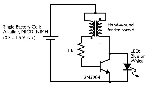
This circuit is commonly referred to as a Joule Thief, and it has been frequently encountered in various electronics videos on YouTube. The Joule Thief is a simple, low-cost circuit designed to extract energy from a single-cell battery, particularly when...

The E1T counting tube is one of the most fascinating tubes ever created. Developed by Philips between 1946 and 1954, it has a unique origin story detailed in other studies. A primary challenge in using this tube for clock...