
The Nic Nac Tic Tac Crystal Radio Set

The crystal radio circuit operates on the principle of resonance, where the combination of the inductor and capacitor forms a tuned circuit. This tuned circuit is critical for selecting the desired radio frequency, allowing the radio to filter out unwanted signals. The inductor (L1) is typically constructed from a coil of wire, which creates a magnetic field when current flows through it, while the capacitor (C1) stores electrical energy. Together, they create a resonant frequency determined by their values, allowing the user to receive specific AM stations.
The diode (D1) serves a dual purpose: it rectifies the incoming radio signal, converting the alternating current (AC) radio wave into direct current (DC), and it acts as a detector, allowing the audio signal to be extracted from the carrier wave. This is essential for audio reproduction, as it enables only the desired sound signal to be sent to the earphone.
The earphone (EP) in this circuit is a piezoelectric device that converts electrical signals into sound. When the small audio signal from the diode is applied to the piezo crystal, it vibrates, creating sound waves that can be heard by the listener. The use of a piezo crystal allows for efficient sound reproduction even with the low power levels typical of crystal radios.
In summary, the crystal radio circuit is a simple yet effective design that illustrates fundamental principles of electronics, including resonance, signal detection, and audio reproduction. The basic components work together to create a functional AM radio receiver, demonstrating the enduring appeal and educational value of crystal radios in the field of electronics.Crystal radios have been around for over 100 years and exist in many different shapes, sizes and complexities. Some are definitely better than others, but wired correctly and connected to a good Antenna and Ground wire system, this simple little AM radio receiver should pull in at least one strong local radio signal for you to listen in to.
In dia gram 1 you can see the basic layout of the `crystal set`. They are called crystal sets, as the original designs used a special material called galena or pyrite, as the detector element, which picks out the sound wave from the radio wave. These crystals have been replaced with a modern component called a diode, and we`ll get to use one of those as we put this kit together.
Signals from your local AM radio stations are traveling through the atmosphere at the speed of light, and they pass through just about everything. These signals hit your antenna wire and induce a small signal current that flows down into the radio`s tuned circuit, and out through the ground wire, to Earth.
The coil, L1 and fixed capacitor, C1, form the `tuned circuit` in our project, in conjunction with the antenna/ground wire system, which enables the receiver to select one station`s frequency and reject the rest. This may seem like a limitation on the radio, but once you`ve got this simple receiver going, you can add one or two more parts in order to make a `tunable` version that can tune across part or all of the AM radio band, for just a couple of dollars more.
All you have to do is swap several parts of differing values around, (included in your kit, ) until you receive a reasonably strong local AM radio station! Experimenting is half of the fun with these circuits. The frequency selected by this process is comprised of two parts - the `carrier wave` which is the radio station`s fixed frequency (its `spot` on the dial of a transistor radio set) and the `program signal` which is the voice, music, secret sound, which originates inside the radio station`s studio.
This is the signal that we want, and the next component, the diode, D1, enables the sound or audio signal, to be split away from the carrier wave. This is called the `detector` because it detects the sound signals contained inside the carrier wave.
Finally, the sound waves that we want are produced in the earphone, EP, as the diaphragm inside the earphone vibrates in unison with the signal coming from the diode, returning through the `link` wire to ground, and thus completing the second `detector/earphone` circuit. Resistor, R1 provides stability for pietzo or crystal earphones, as these devices need a direct path to ground for them to work properly and not distort the signal.
At a chosen frequency a special effect called "resonance" occurs. This simply means that when the coil and capacitor working together as the `tuned circuit` have received the one particular frequency they were set for, then maximum power transfer from transmitter to receiver will occur. All other radio station`s signals will be fed out to earth by the ground wire, and the one you want will be playing away in the earphone.
Our earphone has a special material called `pietzo crystal` and when a small signal is fed into the crystal via the diode and link wire, the crystal will actually vibrate in unison with the signal. This crystal is flat and round, and is attached to a larger piece of tinfoil, which vibrates too, reproducing sound waves that we can hear.
In the diagram at left, you can see the circuit for our simple AM band crystal radio set. It has just four components - a capacitor, C1 which together with the next component, the inductor L1, which stores radio energy and helps tune the radio to one station. Thirdly, there`s the diode D1, which separates the program signal (the voice, music, secret sound) from the radio station`s transmitting frequency, and finally, the resistor R1, which forms a signal return path to gr
🔗 External reference
Related Circuits

Specializing in unique and hard-to-find CB radio books, plans, kits, modifications, repairs, technical information, and high-performance CB accessories since 1976. The focus on CB (Citizens Band) radio equipment encompasses a wide array of products and services tailored to enthusiasts and...
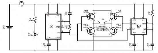
The electronic dog repellent circuit diagram below features a high-output ultrasonic transmitter designed primarily to function as a repeller for dogs and cats. The electronic dog repellent circuit utilizes an ultrasonic transmitter to emit sound waves at frequencies above the...
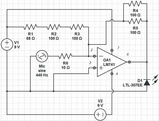
Red = V+, Black = V-, Green = GND, Yellow = Mic Input, Orange = LED Output. The op-amp used is an LM741, which is intended to adjust the peak brightness of the LED based on the ambient sound...

A crystal tester circuit is straightforward, comprising only an oscillator and a detector. This circuit utilizes a single transistor for the oscillator. The crystal tester circuit is designed to evaluate the performance and functionality of crystals, which are essential components in...
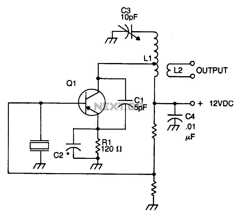
The crystal element in this circuit is connected directly between the base and ground. Capacitor C1 is utilized to enhance feedback due to the internal capacitances of the transistor. This capacitor should be positioned as close as possible to...
The shunt-feedback configuration facilitates the straightforward integration of frequency-dependent networks, enabling a functional and discreet switchable tilt control (optional). When SW1 is in the first position, a gentle shelving bass boost and treble attenuation occur. The central position of...