
The Second W9VES

The schematic of the TNT transmitter utilized by Phil Simmons features a single Type 45 triode tube. The oscillator circuit consists of a plate circuit and a grid circuit, where the plate circuit is responsible for setting the frequency of oscillation. The grid circuit is tuned through an inductance that resonates based on its distributed capacitance and the capacitance between the grid and filament of the tube. This design allows for effective frequency control and stability in transmission. The regenerative detector in the TRF receiver amplifies weak signals, followed by additional audio amplification stages to enhance the overall output. The schematic of the one-tube transmitter by Charles Caringella illustrates a straightforward grid-plate oscillator configuration, which is suitable for novice operators. The integration of a 6C4 triode in later modifications demonstrates the adaptability of the circuit, allowing for improved performance and operational flexibility in various conditions. Overall, these designs encapsulate the evolution of amateur radio technology and the personal experiences of those who have contributed to its development.The amateur radio call sign W9VES has been assigned to ”held by, as ham radio operators like to put it ”only two people, of whom I am the second. My maternal uncle, Phil Simmons, was the first W9VES, and I enjoy my amateur radio in celebration of him.
By mid-2008 CE, the expanding sphere of Effect created by his first transmission in 1935 CE sp anned a diameter of 146 light-years. A W9VES QSL card from 1935 CE. The transmitter used a Type 45 triode tube operating at 8 W input in a TNT (tuned, not tuned) circuit, a special case of the tuned-plate, tuned-grid oscillator; that four-tube TRF (a receiver consisting of a regenerative detector preceded by a tuned RF stage and followed by two stages of audio amplification) would have been a loan from 14-year-old Phil`s friend and chief engineer, George H. ("Bud") Nibbe, W9NUF. The station location at 1618 Juneway Terrace overlooked southern Evanston across the northernmost back alley in Chicago.
The schematic diagram of Phil`s TNT transmitter, a single-tube oscillator, would have looked much like this. The plate circuit (bold lines) determines the oscillator`s frequency; the grid circuit is haphazardly tuned by an inductance that resonates at a frequency determined by its own distributed capacitance and the tube`s grid-to-filament capacitance.
Phil`s friend and chief radio engineer George H. "Bud" Nibbe made print in "Strays" on page 52 of October 1935 QST with his 5-meter-transceiver-equipped bike. Nibbe would die at 42; Phil, six years later, at 47. While building up the gumption to take the Novice amateur radio license examination as a teenager, I bought a little yellow Editors and Engineers paperback book, Easy to Build Ham Radio Projects by Charles Caringella, W6NJV.
Its simplest construction project, "Novice Transmitter for 80 or 40 meters, " consisted of a grid-plate crystal oscillator that used a 5763 transmitting beam power vacuum tube. By mail, from Lafayette Radio on Long Island, I bought a small aluminum chassis to house it. The rest of its components came from the parts collection ”junkbox in ham-radio speak ”of my father, who has operated amateur radio station W9BRD since the late 1930s CE.
Schematic diagram of the one-tube transmitter by Charles Caringella, W6NJV. The circuit is a "grid-plate" (aperiodic tri-tet) oscillator. The popular Ameco AC-1 beginner`s transmitter used a 6V6GT tube in essentially the same circuit. Although I completed the transmitter to the point of dimly lighting an incandescent lamp with its radiofrequency (RF) power output, I never went on the air with it. I was persuaded by my ham-radio mentor ”my Elmer, by ham-radio tradition ”that I would be disappointed with its low power.
He was accustomed to using an outdoor, tower-mounted antenna and running as much power as the law allowed, and he knew that I would begin my ham career with my father`s quasi-indoor antennas. And so I put the little 5763 transmitter aside, later going on the air for the first time, as WN9CJS, Norridge, Illinois (near Chicago), with a more-powerful Lettine Model 240 transmitter, once owned by the first W9VES.
The Lettine used a 6L6GB crystal oscillator driving an 807 power amplifier, and likely put out perhaps six times the RF power of the 5763 oscillator. Later, per an article in QST (Donald Mix, W1TS, "A Simple Transmitter for the Beginner, " Beginner and Novice, QST, September 1968 CE, page 22), I would add a 6C4 triode crystal oscillator to the 5763 circuit and enjoy many solid contacts and several radio adventures with the modified transmitter, including working KH6ALD, Hawaii, on 40 meters during a middle-of-the-night thunderstorm.
(I would also discover that the transmitter still acted as a crystal oscillator with the 6C4 stage disabled, a common characteristic of the Boosted Pierce. ) And later still I would discover, using transmitters with output powers from 6. 3 milliwatts to 20 watts or so, some usi 🔗 External reference
Related Circuits
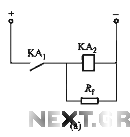
The circuit depicted in Figure 6-24 includes a relay coil with both ends connected in parallel to either a resistor Rf or an auxiliary diode VD. This configuration is equivalent to providing power after a short circuit, which increases...
The schematic below illustrates the division of a crystal oscillator signal by the crystal frequency to obtain an accurate 1-second time base with a precision of 0.01%. Two cascaded 12-stage counters (CD4040) form a 24-stage binary counter, and the...
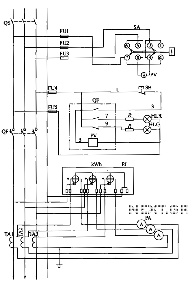
The BSL is illustrated in a low-voltage distribution panel wiring diagram. It consists of three main components: the voltage measuring circuit, secondary circuit protection, and the energy metering circuit. (1) The voltage measuring circuit includes a voltage switch (SA)...
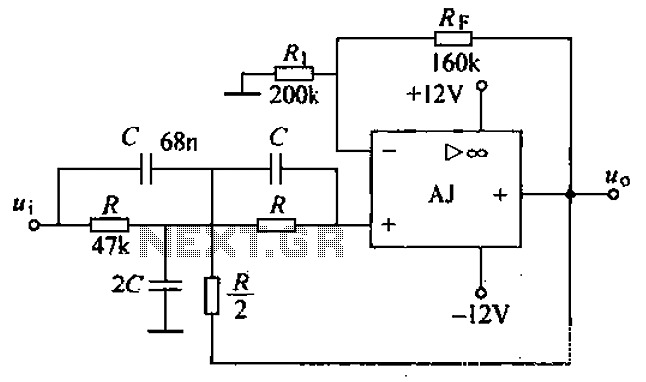
A band-stop filter (BSF) utilizing an integrated operational amplifier is designed to suppress signals within a specific frequency band, allowing signals outside this band to pass with minimal attenuation. This configuration is achieved through a two-stage network, which employs...

This filter circuit, which utilizes the LM1458 or a similar operational amplifier, has a frequency response ranging from 300 Hz to 3.4 kHz, exhibiting a roll-off of 12 dB per octave outside the passband. Section A serves as the...
This precise one-pulse-per-second clock is constructed using a few common components and is powered by a 50 or 60 Hertz mains supply without any direct connection to it. A beep or metronome-like click, along with a visible flash, indicates...