
The simple LED Flasher by IC 4011

The LED flasher circuit operates by utilizing a basic astable multivibrator configuration, which can be implemented using two transistors. This circuit alternates the state of the output, causing the connected LED to flash on and off at a specified frequency.
The core components of the circuit include two NPN transistors, resistors, capacitors, and a single LED. The transistors are arranged in a feedback loop where the output of one transistor is connected to the base of the other, allowing for continuous oscillation. The timing of the flashing is determined by the values of the resistors and capacitors selected for the circuit.
In a typical setup, the circuit begins with one transistor in the "on" state, which allows current to flow through the LED, causing it to illuminate. As the capacitor connected to the base of this transistor charges, it eventually reaches a threshold voltage that turns the transistor off. This action simultaneously turns the second transistor on, creating a cycle that repeats itself.
The frequency of the flashing can be adjusted by changing the capacitance or resistance values. For example, increasing the capacitance will result in a slower flash rate, while reducing the resistance will speed up the flashing.
This LED flasher circuit serves as an excellent introduction to basic electronic principles, including the behavior of transistors, capacitors, and resistors in a timed application. It is a practical project for beginners to gain hands-on experience with electronic components and circuit design.This is simple a led flasher circuit that I would link to suggest you make it.But before you can use transistors,which difficulty when we learn about digital.. 🔗 External reference
Related Circuits

This single-chip circuit adjusts its audio gain according to the ambient noise picked up by the microphone. When operating in a quiet environment, the audio output is quiet, while a noisy environment results in a louder audio output. Audio...

These are simple AVR programmers. I designed and built four different programmers for various environments: LPT controlled parallel programmer, LPT controlled ISP adapter, COM controlled ISP adapter, and COM controlled generic SPI bridge. Additionally, COM controlled adapters can be...

In this application, a BA1404 is utilized to generate an FM MPX baseband signal. This signal modulates a crystal oscillator (Q3) through a dual varactor series modulator. This transmitter can be used to play CD audio on an existing...

This simple circuit can be used to flash incandescent lamps with a power rating of up to 10W. It is ideal for creating flashing beacons on automobiles and similar applications. The circuit consists of an astable multivibrator utilizing transistors...
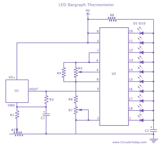
An LED thermometer that can function as a temperature sensor or temperature measurement circuit, utilizing the LM34 for Fahrenheit display or the LM35 for degree Celsius display. The LED thermometer circuit is designed to provide accurate temperature readings using either...

This circuit is a simple series tone control circuit. It utilizes the surgical amplifier LM301A. The JFET 2N3684 provides high input impedance and low noise for the unbuffered operational amplifier, which operates in an equalizer (EQ) configuration. Further details...