
The Simplest Car Battery Charger

The circuit described functions as a straightforward battery charger utilizing a transformer, two diodes, a smoothing capacitor, and an ammeter to monitor the charging current. The transformer steps down the AC voltage from the mains supply to a lower voltage suitable for battery charging. The two diodes are configured in a full-wave rectifier arrangement, allowing both halves of the AC waveform to be utilized, which improves the efficiency of the charging process.
When the circuit is powered, the AC voltage from the transformer is rectified by the diodes, converting it into pulsating DC voltage. The smoothing capacitor is crucial in this configuration as it reduces the ripple in the output voltage, providing a more stable DC voltage to the battery. This is particularly important when the circuit is used as a battery eliminator, where a steady voltage is required for devices that operate on 12V DC.
The ammeter is an essential component for monitoring the charging current flowing into the battery. A reading of 1-3 amps indicates that the battery is in the charging phase. As the battery approaches full charge, the current diminishes, and the ammeter will eventually read zero or nearly zero. This behavior is a signal to disconnect the battery to prevent overcharging, which can damage the battery.
It is imperative to connect the + and - terminals correctly to avoid damage to the circuit and the battery. Reversing the polarity can lead to circuit failure or battery damage. Overall, this circuit efficiently charges a battery while providing essential feedback through the ammeter, ensuring safe and effective operation.This very simple circuit uses a transformer ,two diodes , a capacitor and an ammeter. To charge a battery just connect the + and - terminals of the circuit to the corresponding terminals of the battery. When the battery is not charged, the ammeter reading shows 1-3 amps. When the battery is fully charged the ammeter reads Zero or nearly zero, after which the battery should be removed from the charger.
The circuit is a full wave rectifier using 2 diodes for rectification. The capacitor is used for smoothing. I think the circuit works fine without the capacitor since the battery itself acts a BIG capacitor. But when you are using the circuit to supply 12V (as a battery eliminator) the capacitor needs to be present. Care should be taken NOT to reverse the + and - terminals while connecting it to the battery. 🔗 External reference
Related Circuits
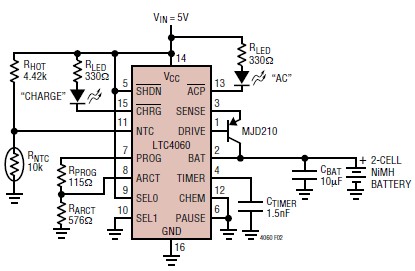
The LTC4060 integrated circuit can be utilized to create a straightforward smart NiMH battery charger electronic project. This charger circuit functions as a complete fast charging system for NiMH or NiCd batteries. It requires only a few external components...
The schematic consists of four hardware blocks: 1) The wall transformer 2) The charging circuit 3) The control unit 4) The output stage. The circuit schematic is structured around four essential hardware blocks that facilitate the overall functionality of the...

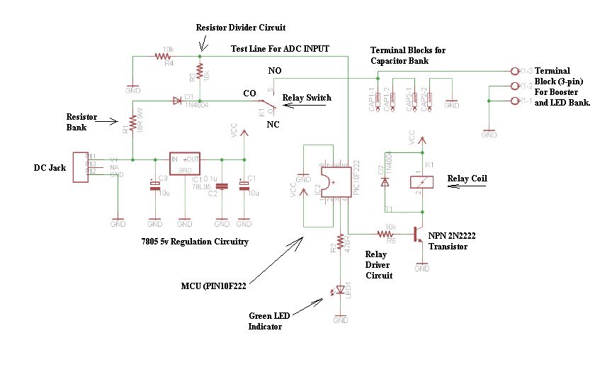
This circuit provides a simple and efficient method to draw current from a motorcycle battery to charge a mobile phone. Most mobile phone battery packs consist of three 1.2-volt cells, resulting in a total voltage of 3.6 volts. For...
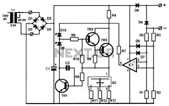
A clever charger circuit that safely charges any Ni-Cd battery. It offers charge current selection, polarization detection, protection, and the ability to connect multiple batteries in series. Ni-Cd batteries can be recharged more than 1000 times before becoming unusable....

The trembler (motion-activated) switch triggers an alarm for 5 seconds before automatically turning off. The circuit has a timeout period of 10 seconds to allow the trembler switch to stabilize. The trembler switch circuit operates by detecting motion through a...
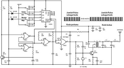
The following circuit illustrates a schematic diagram for a remote control toy car. Features: it does not interfere with the performance of the original design. The remote control toy car circuit typically consists of several key components that enable wireless...