
The Super Capacitor Flashlight with Custom Charger and Voltage Booster

The circuit schematic is structured around four essential hardware blocks that facilitate the overall functionality of the system.
1. **Wall Transformer**: This block serves as the primary power source, converting the high-voltage AC from the mains supply into a lower voltage AC suitable for the circuit's requirements. Typically, a step-down transformer is employed to achieve the desired voltage levels, ensuring safe operation of subsequent components.
2. **Charging Circuit**: The charging circuit is responsible for converting the AC voltage from the wall transformer into a stable DC voltage. This is usually accomplished using a rectifier (either full-wave or half-wave) followed by a smoothing capacitor to filter out ripples, providing a steady DC output. This voltage is crucial for powering the control unit and other components effectively.
3. **Control Unit**: The control unit acts as the brain of the circuit, managing the operation of the entire system. It may incorporate a microcontroller or a dedicated logic circuit that processes input signals, executes programmed instructions, and controls the output stage based on predefined conditions. This block may also include various sensors and feedback mechanisms to monitor performance and adjust parameters dynamically.
4. **Output Stage**: The output stage is designed to deliver the final output of the circuit, whether it be a signal, power to another device, or any other form of output. This block may consist of amplifiers, drivers, or other components that ensure the output is at the required levels and formats for the intended application.
Each of these blocks is interconnected through a series of conductive paths, with careful attention paid to component ratings and specifications to ensure reliability and efficiency. The overall design must also consider aspects such as thermal management, electromagnetic compatibility, and safety standards to ensure optimal performance in real-world applications.Before I begin talking about the schematic, let it be known that there are four hardware blocks to this circuit: 1) The wall transformer 2) The charge.. 🔗 External reference
Related Circuits
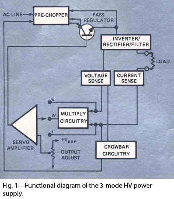
By combining switching and series-pass techniques, the designer of this high-voltage supply achieved 0.01% regulation at power levels up to 100W. The high-voltage power supply employs a hybrid approach that integrates both switching and series-pass regulation methods to achieve exceptional...
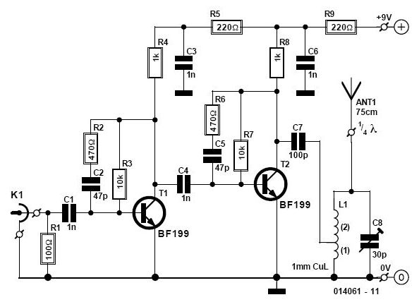
This AM/FM antenna booster circuit amplifies the broadband signal from the antenna. This antenna booster is designed to work for FM, AM, and SW receivers. The AM/FM antenna booster circuit is an essential component for enhancing radio reception across...
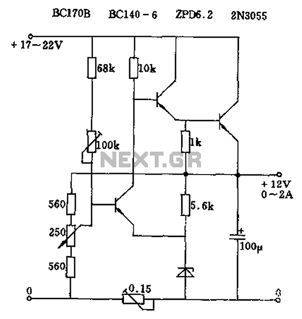
The circuit output voltage can be continuously adjusted from zero to its maximum value. The baseline is established by a constant current sourced from the auxiliary power supply circuit. The reference current of 500 microamperes can be fine-tuned to...
This circuit is a high input voltage regulator that generates a voltage of 5V. In this circuit, the input voltage for the LM340 must remain within the limits specified in the datasheet. Operating the device above the absolute maximum...

This is a simple and low-cost NiCd and NiMH battery charger. The schematic diagram indicates that the charging current (I) should be set to 1/10 of the battery's rated capacity. For instance, if the battery has a rated capacity...
This circuit enables the use of a portable VHF FM radio to receive audio from stations that exclusively broadcast on the local cable network. This circuit operates by modulating the audio signals from the local cable network onto a carrier...