
The Star-Delta 3-phase Motor Starting Method

The Star Delta starting method is widely employed in industrial applications to reduce the electrical stress on motor windings and the associated power supply during startup. The configuration begins with the motor connected in a Star (Y) configuration, which effectively reduces the voltage across each winding to 58% of the line voltage. This reduction in voltage results in a corresponding reduction in starting current, thus minimizing the initial inrush that can cause damage to both the motor and the electrical infrastructure.
Once the motor reaches approximately 70-80% of its rated speed, the control system switches the motor from the Star configuration to the Delta (Δ) configuration, allowing full line voltage to be applied. This transition is typically managed by a control relay or timer, which ensures that the switch occurs at the correct moment to maintain operational efficiency and protect against excessive current draw.
The three contactors play a crucial role in this setup. The Main Contactor connects the motor to the power supply, while the Star and Delta contactors are responsible for switching the motor between the two configurations. Proper interlocking between these contactors is essential to prevent simultaneous engagement, which could lead to short circuits or damage to the motor.
In addition to the contactors, it is standard practice to incorporate overload relays and fuses within the circuit to provide protection against overload conditions and short circuits. The overload relay monitors the current flowing to the motor and disconnects the power supply if the current exceeds a predefined threshold, thus safeguarding the motor from damage.
In summary, the Star Delta starting method is an effective solution for managing the starting characteristics of induction motors, particularly in high-power applications. Its ability to reduce inrush current not only protects the motor but also enhances the longevity and reliability of the entire electrical system.The Star Delta starting method is a motor starting mechanism that minimizes the large amount of starting current that motors draw in. The Star Delta, as the name suggests basically involves feeding the motor with 1/sq. root3 (58%) of the full load current until it attains speed then applying the full load current. This method is commonly referred t o as "Soft Starting" the motor, For this to work the whole set-up requires 3 contactor i. e The Star Contactor, The Delta Contactor & The Main Contactor. However for the motor to be started in Star Delta, its internal connection at the terminal box has to be wired in Delta-giving it capability of receiving the full-load current at any instant. Traditionally, in many regions there was a requirement that all motor connections be fitted with a reduced voltage starter for motors greater than 4KW 5HP.
This was to curb the high inrush of starting currents associated with starting induction motors. 🔗 External reference
Related Circuits
These circuits could be used as the basis for Model Railroad DCC Boosters or PWM motor controllers. The first schematic is for a basic 3 Amp - DCC Booster using the LMD 18200 CMOS, H-Bridge. Included in the design...
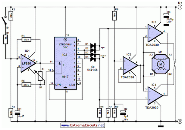
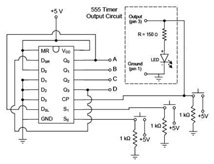
Stepper motors are available in several versions and sizes with a variety of operating voltages. The advantage of this general-purpose controller is that... Stepper motors are electromechanical devices that convert electrical energy into precise mechanical movement. They are widely used...
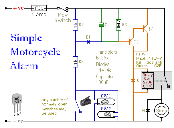
When one of the switches is closed, the base of Q1 is connected to ground through D1 and R2. This activates Q1, which in turn activates Q2. Q2 connects the positive side of the relay coil to the supply...
PWM is a device that can be utilized as an efficient light dimmer or DC motor speed controller. Function: for a general-purpose device that can... PWM (Pulse Width Modulation) is a versatile technique widely employed in various electronic applications, particularly...
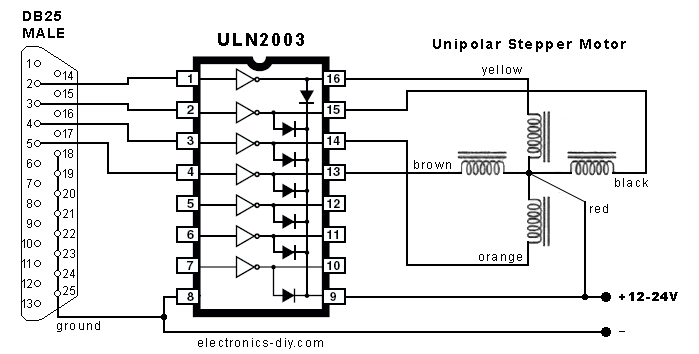
In the search for stepper drivers, the ULN2003 chip was discovered, which facilitates motor operation with minimal circuitry through the parallel port of a PC. However, the current output from the ULN2003 is limited to 500mA, resulting in low...
A motor coil requires controllers to adjust its position and speed. A motor driver is necessary to amplify the low output current from a controller to a larger current required by the motor. The following article describes how to...