
Thermometer For 5V Operation Circuit

The KTY10 temperature sensor operates on the principle of varying resistance with temperature changes. As the temperature increases, the resistance of the sensor decreases, which alters the balance of the bridge circuit. This unbalance generates a voltage differential that is read by the moving coil meter (M1). The meter's scale can be calibrated to reflect temperature readings accurately, allowing users to interpret the value directly.
The bridge circuit configuration enhances sensitivity and accuracy, making it suitable for precise temperature measurements. The use of a temperature-compensated Zener diode ensures that the voltage supply remains stable despite variations in ambient temperature, which could otherwise affect the performance of the sensor and the meter readings.
For applications requiring a more portable solution, utilizing a 9-V battery can be advantageous. By substituting the specified components with a voltage regulator, the circuit can maintain efficient power consumption, extending the operational life of the battery while providing reliable temperature readings. This flexibility in power supply options makes the circuit adaptable for various applications, whether in laboratory settings or field measurements.
Overall, this temperature measurement circuit exemplifies a straightforward yet effective design, leveraging the characteristics of the KTY10 sensor and a bridge configuration to deliver accurate temperature readings across a range of conditions. At the heart of this simple circuit is the well-known type KTY10 temperature sensor from Siemens. This silicon sensor is essentially a temperature-dependent resistor that is connected as one arm in a bridge circuit here. Preset PI functions to balance the bridge at 0C. At that temperature, moving coil meter Ml should not deflect, i.e., the needle is in the center position.
Temperature variations cause the bridge to be unbalanced, and hencc produce a proportional indication on the meter. Calibration at, say, 20C is carried out with the aid of P2. The bridge is fed from a stabilized 5.1-V supply, based on a temperature-compensated zener-diode. It is also possible to feed the thermometer from a 9-V battery, provided D1-D3, Rl and Cl are replaced with a Type 78L05 voltage regulator, because This is more economic as regards to current consumption.
Related Circuits

The circuit depicted is designed to protect a system from power supplies that may exceed safe limits. An example of this is small consumer products that utilize external AC adapters, where there is a risk of accidentally connecting the...
This circuit is designed to detect whether the load of a battery charger or plug-in adapter is properly connected. The load may consist of a set of batteries needing charging or any other device that operates on low DC...
The circuit is designed to set a delay time based on the voltage Us and the resistor R. In this configuration, S1 acts as the discharge switch for capacitor C. When switch S1 is closed, the stored charge in...
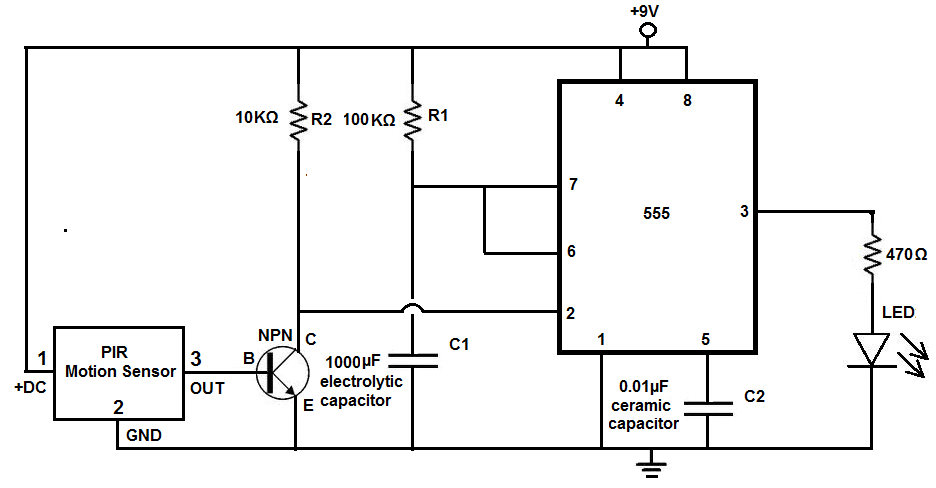
Many individuals install motion detectors in their backyards or homes to automatically turn on lights when movement is detected. Motion sensor lights have gained popularity and are increasingly utilized in various settings. Businesses frequently employ them in bathrooms, where...
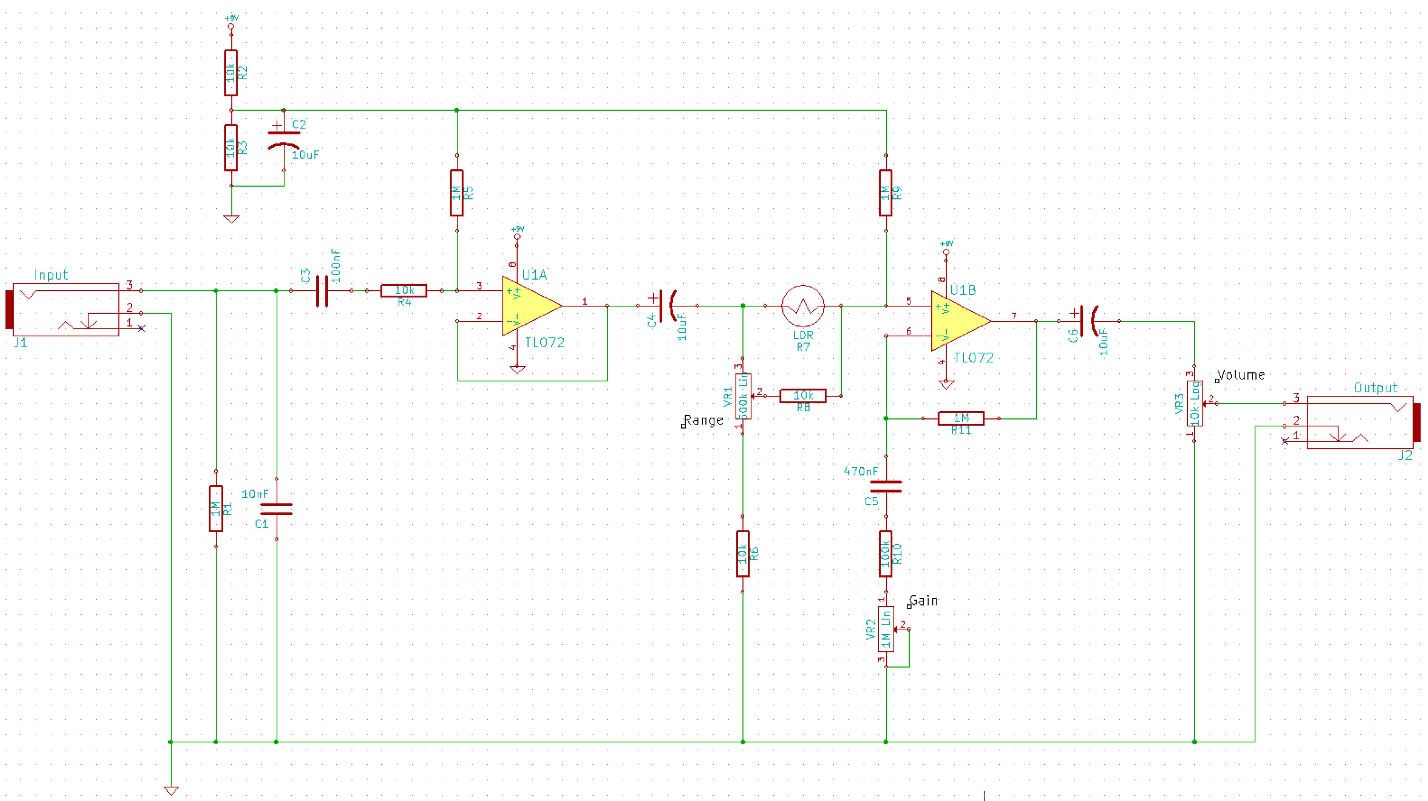
This is a simplified schematic for the Solar Lifeforce. The design eliminates the expression/CV output features and the toggle for the buffer, making it a straightforward circuit. It may benefit from adding small capacitors between R5 and ground, as...

Many brands in Asia utilize ultrasonic remote control switch circuits, with some employing relays and others utilizing thyristors. The remote control transmitter is of a puffer type, featuring an ultrasound flute with both olive and flat circular shapes. This...