
Thermometer meter slinger 2

The thermometer meter slinger circuit is designed to provide precise temperature measurements while allowing for adjustable timing control of the meter slinger mechanism. The power supply circuit is essential for converting AC voltage to a usable DC voltage, ensuring that all components receive the necessary power for operation. The fuse (FU) is a protective element that prevents overcurrent conditions, while the power supply buttons (S) allow users to turn the circuit on or off. Resistors (R1, R2) and capacitors (C1, C2) are used to filter and stabilize the power supply output, with the LED (VL) providing visual indication of power status.
The timing control aspect of the circuit is crucial for the operation of the meter slinger. Resistors (R3, R4) and the potentiometer (RP) work together to set the time constant for the charging of capacitor C3. By adjusting the potentiometer, the user can change the resistance in the timing circuit, thereby altering the charge time of C3. This adjustment directly influences the duration for which the relay (K) is activated, controlling the operation of the motor (M). The relay acts as a switch that can handle higher currents, allowing it to turn the motor on or off based on the timing established by the capacitor's charge.
Capacitors C4 and C5 may also be employed for additional timing or filtering purposes, ensuring stable operation under varying conditions. Diode VD2 serves to protect the circuit from voltage spikes that may occur when the relay coil is de-energized, safeguarding sensitive components. Overall, the design of the thermometer meter slinger circuit integrates both power management and timing control, enabling efficient and accurate temperature measurement applications.The thermometer meter slinger circuit is composed of power supply circuit and meter slinger timing control circuit, it is shown in the figure 9-135. The power supply circuit is made of fuse FU, power supply button S(Sa, Sb), resistors R1, R2, capacitors C1, C2, power supply indication LED VL, steady voltage diode VS and rectifier diodes VD1.
The m eter slinger timing control circuit consists of resistors R3, R4, potentiometer RP, capacitors C3-C5, relay K and diode VD2. C3`s charge time can be changed by adjusting RP, then it can control M`s run time. 🔗 External reference
Related Circuits
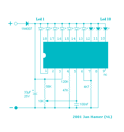
This simple circuit makes it possible to monitor the charging process to a higher level. If you need more information then check out the LM3914 Datasheet. Final adjustments are simple and the only thing needed is a digital voltmeter...
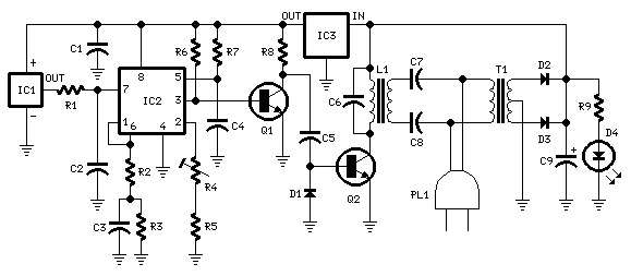
This circuit is intended for precision centigrade temperature measurement, with a transmitter section converting to frequency the sensor's output voltage, which is proportional to the measured temperature. The output frequency bursts are conveyed into the mains supply cables. The...
A simple LED-based voltmeter is required to monitor the voltage of a variable power supply. The proposed LED voltmeter circuit utilizes a series of light-emitting diodes (LEDs) to visually represent the voltage level of a variable power supply. This...
This project is currently under construction and has not been validated for functionality. A signal generator, resistor, and oscilloscope were utilized to measure the value of an inductor for a battery charger project. In the search for an affordable...
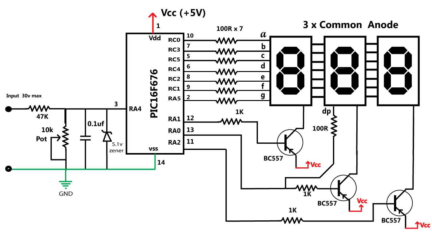
This is a simple application of the internal 10-bit ADC (analog-to-digital converter) of the PIC16F676 microcontroller. This circuit can be used to measure up to 30 V DC. Possible applications include a benchtop power supply or as a panel...
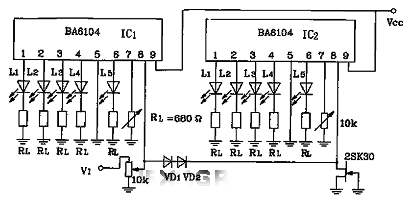
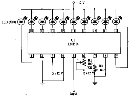
BA6104 is a five-digit LED level meter that functions as an LED display driver integrated circuit (IC). The configuration of the circuit is illustrated in the accompanying figure. The circuit utilizes a 10 by two-dot LED level display. The...