
Universal Power Supply Circuit

The universal power supply circuit is designed to convert alternating current (AC) from the mains into a stable direct current (DC) output suitable for various electronic applications. The bridge rectifier serves as the initial component, consisting of four diodes arranged in a configuration that allows both halves of the AC waveform to be utilized, effectively converting AC to pulsating DC.
The voltage stabilizer, typically represented by the 78xx series, is a linear voltage regulator that maintains a constant output voltage despite variations in input voltage or load conditions. The "xx" in the designation indicates the specific output voltage, which can range from 5V to 24V depending on the model used. The stabilizer's output is connected to the load, ensuring that sensitive electronic components receive a consistent voltage level.
The inclusion of a PNP power transistor in this circuit enhances its current handling capabilities. This transistor acts as a switch or amplifier, allowing for increased load current without overheating or causing voltage drops. When combined with the voltage regulator, the PNP transistor provides additional stability and current support, making the power supply suitable for driving higher power devices.
Overall, this universal power supply design is versatile and can be adapted for various applications, including powering microcontrollers, sensors, and other electronic circuits that require a reliable and stable power source. Proper heat sinking and component selection are critical to ensure efficient operation and longevity of the power supply system.This universal power supply contains, beside the bridge rectifier, a voltage stabilizer (78xx) and a pnp power transistor. This combination allow a load cu.. 🔗 External reference
Related Circuits
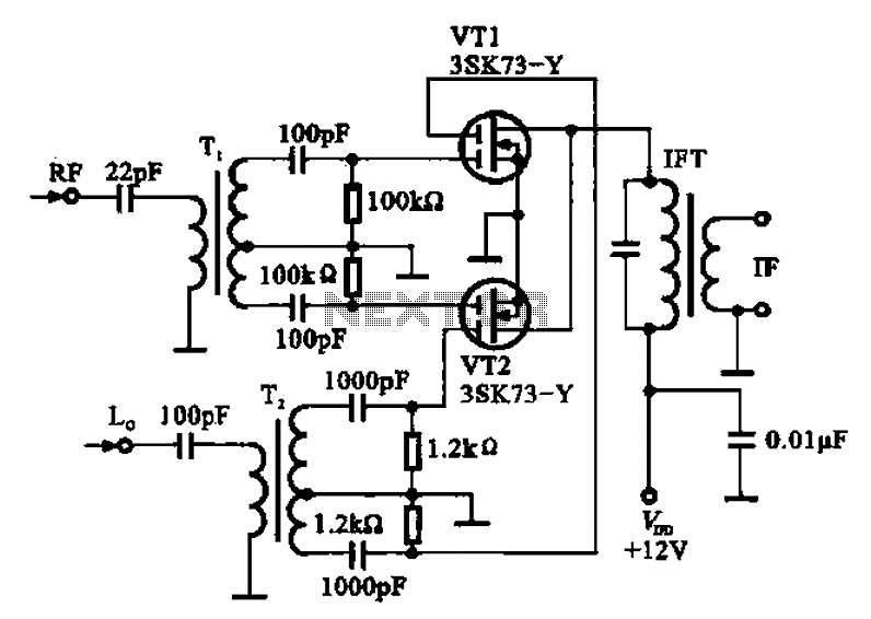
A balanced mixer circuit is illustrated using two dual-gate field effect transistors (FETs). The RF signal is coupled to the gates of these transistors through an input signal transformer (T1). Additionally, a local oscillation signal is introduced to the...
This compact circuit enables automatic recording of phone conversations. It connects to the phone line, the microphone input of a tape recorder, and the remote control jack of the recorder. The circuit detects the voltage level in the phone...
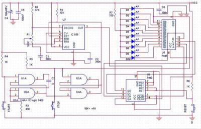
The speed test circuit is a simple design intended to measure a person's reaction time in a game. The operation of this peripheral is straightforward, facilitated by several integrated circuits, including a counter, timer IC, and decoder. The timer...
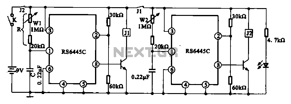
The timing integrated circuit (IC) RS6445C functions as a blocking oscillator. It features two segments, WI and W2, which are utilized to adjust the working time and the closure time. These adjustments can be continuously set within a range...
When signing into developerWorks for the first time, a profile is automatically created. Certain information from this profile, such as name, country or region, and company, is made public and will be associated with any content posted. Users have...
A rain sensor alarm circuit is a useful device for alerting when rainfall occurs. The rain detector circuit presented is straightforward, utilizing only three components while maintaining high sensitivity to detect rain or moisture. The sensor can be constructed...