
Timer circuit

The described circuit employs an ATTiny15 microcontroller as the core component, utilizing its internal oscillator for timing control. The user can set the desired time duration using a potentiometer, which adjusts a variable resistor in the circuit, influencing the time constant. The potentiometer's resistance value is converted into a digital signal that the microcontroller interprets to determine the timing period.
The pushbutton switch serves as the user interface for initiating the timing sequence. Upon pressing the button, the microcontroller activates a relay, which could control an external load, such as a lamp or other devices. The relay remains energized for the duration specified by the user, and the microcontroller monitors the elapsed time. Once the pre-set time expires, the microcontroller sends a signal to deactivate the relay, effectively turning off the connected device.
Calibration of the internal oscillator is critical for achieving accurate timing. The OSCCAL register is adjusted to ensure that the microcontroller generates a precise 10 ms pulse width. This calibration process may involve several iterations to account for variations in the oscillator's frequency due to environmental factors or manufacturing tolerances.
The capability to switch the timer to seconds for shorter durations enhances the circuit's versatility, making it suitable for tasks requiring precise timing, such as cooking or charging batteries. The adjustment of cnt_cmp allows for easy modification of the timing range, accommodating various application needs.
The inclusion of PB4 for initiating the timer adds further functionality. This pin can be connected to various sensors, such as an LDR, enabling the circuit to operate based on environmental conditions. The design prevents false triggers by ensuring that the timer can only be reset by a high signal on PB4 after the timer has completed its cycle, thus enhancing reliability in practical applications.
Overall, this circuit design provides a robust and flexible solution for timing applications, with user-friendly adjustments and reliable operation based on the ATTiny15 microcontroller's capabilities.The time can be set with a potentiometer between 1 minute and 1023 minutes, about 17 hours. A pushbutton starts the time, turns on a relais and the timer will turn off the relais when the time is elapsed. It can be switched to seconds for a shorter time period (17 minutes) e. g. to boil eggs, also easy to forget about. The ATTiny15 is using an inte rnal oscillator only and needs a calibration for a 10 ms high pulse on PB1, so it is necessary to write a good calibration byte to the OSCCAL register, which is in the beginning of the program OSCCAL_val= 0x6F. It`s a bit of trial and error until the 10 ms are set for your contoller but is should be done. The total time is not extremely accurate because we can`t use a quartz, but for a battery charger I think it is good enough, the batteries don`t mind a few minutes more or less.
However, time setting with a potentiometer is quick and easy. If 17 hours are not sufficient and a longer time is required it is possible to change the value of cnt_cmp = 100 ; 100 * 10 ms = 1 second in the program to e. g. cnt_cmp = 200, which will double the time to 34 hours. Depending on your application the time can also be much shorter, change cnt_cmp accordingly. Any high to low transition on PB4 will start the timer, even a LDR could be connected to PB4 to make a light switch which turns on for the preset time when it is dark.
It will turn off even if PB4 is still low and then waits for the switch or LDR to go high again. This also prevents a false trigger when the time is short and the button is still pressed. It is quite flexible and can be adapted to many applications which need a timer. 🔗 External reference
Related Circuits
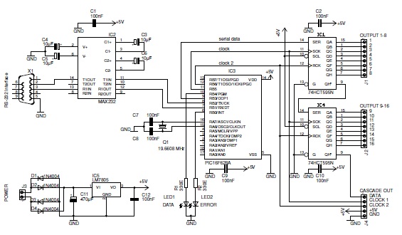
This basic PIC-based RS-232 serial interface can control up to 120 digital TTL outputs. The described circuit utilizes a PIC microcontroller to facilitate communication via the RS-232 protocol, which is a standard for serial communication. The interface primarily serves to...
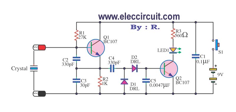
A multimeter cannot be used to test a crystal oscillator. Instead, a dedicated circuit is required, capable of checking crystals within the frequency range of 100 kHz to 900 MHz. This circuit is easy to construct and cost-effective. To construct...
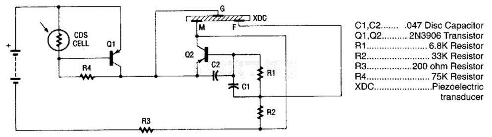
The alarm utilizes a fixed-frequency piezoelectric buzzer alongside a cadmium-sulfide (CDS) cell and a two-transistor circuit to create a distinctive effect. When light reaches the CDS photoelectric cell, the alarm remains silent. However, in the absence of light, transistor...

This design circuit is a tone control circuit that utilizes the popular Baxandall configuration, a straightforward circuit layout that allows for continuous boost and cut control. The circuit is inexpensive to construct and is frequently implemented in commercial products....

The cookers pot quality detection circuit is designed to assess the quality of cooking pots. The testing process utilizes a disc lesion-induced voltage (EMF) to determine the pot's quality. The cookers pot quality detection circuit employs a method based on...

This sensitive FM radio tuner is an ideal circuit for hobbyists who wish to construct their own tuners rather than purchasing a pre-assembled product. The FM radio tuner circuit is designed to receive frequency modulation signals, providing a clear and...