
Tickler oscillator circuit

For constructing a capacitor: Step 1 involves creating a capacitor using two rolls of Saran Wrap and aluminum foil. Lay out aluminum foil on the Saran Wrap, ensuring that the Saran Wrap extends beyond the foil for insulation. Cut the Saran Wrap from one roll and place it over the other to form a sandwich structure. Insert bare wires into the sandwich to connect with the aluminum layers, then roll the assembly back into the Saran Wrap roll. Step 2 requires taping the capacitor wires to opposite ends of a battery with electrical tape to charge the capacitor for an hour, similar to charging a battery.
The oscillator circuit described utilizes feedback and timing elements to create a stable oscillation. The configuration and choice of components, such as resistors and capacitors, directly influence the behavior and performance of the oscillator. The design allows for flexibility in frequency adjustment, making it suitable for various applications where precise timing and frequency control are essential.When the circuit is first powered up, neither transistor will be switched on. However, this means that at this stage they will both have high base voltages and therefore a tendency to switch on, and inevitable slight asymmetries will mean that one of the transistors is first to switch on. This will quickly put the circuit into one of the above sta tes, and oscillation will ensue. Very roughly, the duration of state 1 (high output) will be related to the time constant R2. C1 as it depends on the charging of C1, and the duration of state 2 (low output) will be related to the time constant R3. C2 as it depends on the charging of C2 ” and these time constants need not be the same, so a custom duty cycle can be achieved.
However, the duration of each state also depends on the initial state of charge of the capacitor in question, and this in turn will depend on the amount of discharge during the previous state, which will also depend on the resistors used during discharge (R1 and R4) and also on the duration of the previous state, etc. The result is that when first powered up, the period will be quite long as the capacitors are initially fully discharged, but the period will quickly shorten and stabilize.
An odd number of inverters are required. Using a minimal number of stages within the oscillator allows for maximum frequencies to be achieved, however this will be sensitive to voltage variations. By using a larger number of stages, the noise, due to voltage variation is minimised. The frequency is not exact due to variations in transition time. This is compensated for by controlling the current passing through the transistors. This also allows you to make it a Voltage controlled oscillator (VCO). OCXO (short for Oven Controlled X-tal (Crystal) Oscillator) is a technique used for avoiding temperature changes that affect the resonance frequency of a piezoelectric crystal.
In electronics, an oscillator is a circuit that generates a signal at a certain frequency. You can make a simple oscillator with an inductor (a coil) and a capacitor (two parallel plates). The circuit will alternately store energy in the capacitors (electrical energy) and in the inductor (magnetic energy). The electrons coming off one plate will pass through the inductor. As the charge on the plates becomes constant, the current dies. The drop in current creates an electromotive force in the inductor that propels electrons to continue in the same direction, thus charging the other capacitor plate.
You`ll Need: Step 1: Create a capacitor as follows, if you don`t have one handy. Unroll two rolls of Saran Wrap a few feet. Place a few feet square of aluminum foil on each unrolled area so that the Saran Wrap extends out farther (covers more area) than the aluminum sheets. This extra extension will provide electrical insulation between the "plates" when the two sheets of Saran Wrap and aluminum are rolled up together again.
Now cut the Saran Wrap at the edge of one of the Saran Wrap rolls and place the newly cut-off Saran Wrap-aluminum sandwich squarely onto the other Saran Wrap-aluminum sandwich. This makes a Saran-Wrap-foil-Saran-Wrap-foil sandwich. The bottom Saran Wrap layer is still connected to its roll of Saran Wrap. Insert two bare wires into the sandwich at different layers to contact the two aluminum sheets. Then roll up the whole thing into the Saran Wrap roll that is still attached to the bottom Saran Wrap layer.
The Saran Wrap layer between the two foil layers keeps them insulated from each other like an air in a conventional capacitor. Step 2: Tape the capacitor wires to opposite ends of a battery with electrical tape. This will charge up the capacitor. Let it charge for an hour, just like you`d charge a battery. 🔗 External reference
Related Circuits
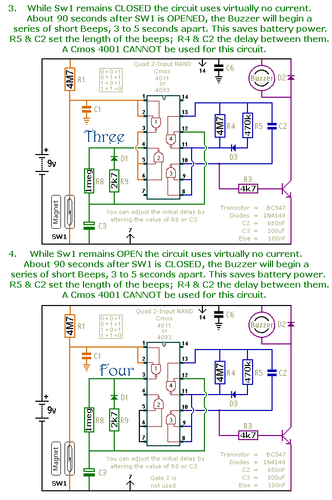
This is a collection of compact, self-sufficient alarm circuits designed for low standby current, making them ideal for battery operation. Some circuits are activated by normally-open and normally-closed switches, while others respond to variations in light or temperature. This...
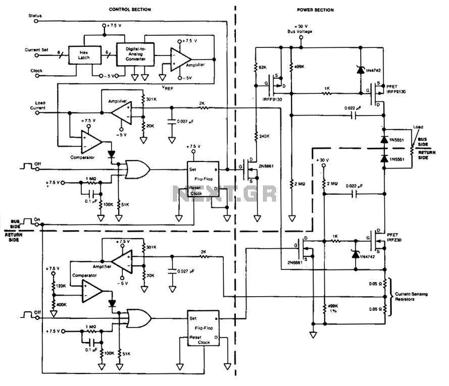
This circuit facilitates on/off switching, soft starting, current monitoring, current tripping, and overcurrent protection for a 30 Vdc power supply, accommodating normal load currents of up to 2 A. The switch is activated by an "on" command pulse and...
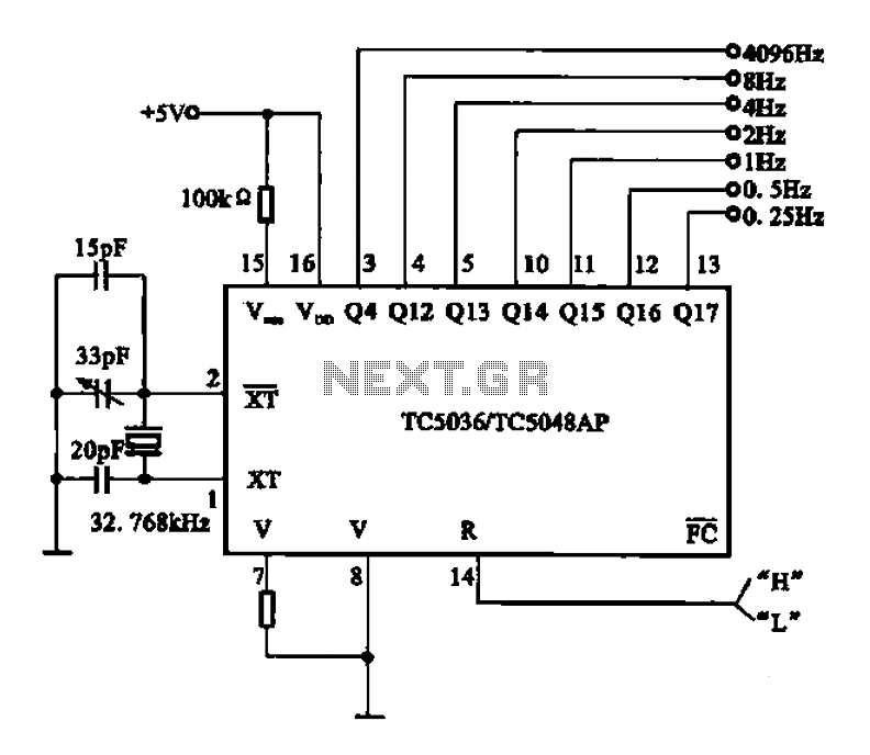
32.768 kHz; In MP3/MP4 devices, mobile phones, laptops, and other digital products, a real-time clock signal generating circuit is utilized, primarily composed of crystal resonators and TC5036/TC5048AP chip oscillators. This setup produces a raw 32.768 kHz crystal oscillator signal,...
This circuit is constructed using two LT1001 operational amplifiers (OP-AMPs), with the output of the OP-AMP saturating at +5V. The power supplies used are +5V and ground. According to the documentation, applying +1V to the "Servo Input" results in...
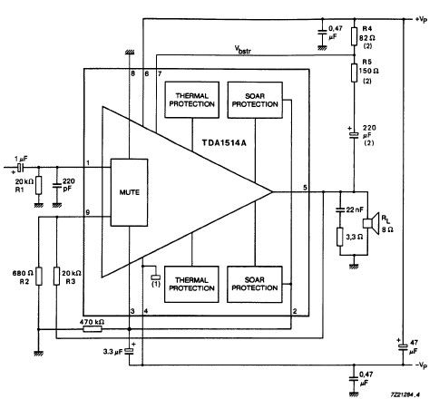
The TDA1514 audio amplifier circuit design is an electronic project capable of delivering high audio power output using a specialized audio integrated circuit (IC) and a few common components. Manufactured by Philips Semiconductor, the TDA1514 audio IC can provide...
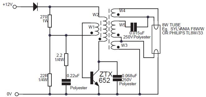
This circuit is an 8W inverter designed to drive an 8W fluorescent lamp from a 12V power supply, utilizing an inexpensive inverter based on a ZTX652 transistor. The inverter operates from power supplies ranging from 10V to 16.5V, achieving...