
Karplus Strong Opamp Circuit

The circuit in question utilizes an LM358 op-amp configured as an all-pass filter, enhanced with additional components to create a unique percussive sound generator. The fundamental operation of the all-pass filter allows for phase shifting of the input signal without altering its amplitude, which is crucial for achieving the desired sonic characteristics. The resistor connected to the non-inverting input serves as a means to inject a stimulus pulse into the circuit, effectively allowing the user to control the timing and triggering of the percussive sounds.
The capacitor connected from the non-inverting input to ground plays a vital role in shaping the frequency response of the circuit. By acting as a low-pass filter in conjunction with the feedback loop, it ensures that higher frequency components are attenuated, allowing for a smoother and more rounded output sound. The specific values of the components—330kΩ for the resistor, 0.1uF for the capacitor, and the additional 2.2uF capacitor—are selected to optimize the filter's performance within the desired frequency range for percussion sounds.
The design's flexibility allows for various configurations by altering the resistance and capacitance values, enabling the generation of multiple percussive tones from a single circuit. The inclusion of a sequencer and white noise generators can further enhance the creative possibilities, allowing for complex rhythmic patterns and textures.
This circuit exemplifies the intersection of filter design and sound synthesis, demonstrating how different electronic components can be combined to create innovative audio effects. The ongoing discussion regarding its classification highlights the complexity of sound synthesis and the various approaches to achieving similar auditory results. The implementation of the Karplus-Strong theory within this circuit illustrates the potential for creating rich, dynamic sounds using relatively simple electronic components.It`s basically just an all-pass filter with two components added: a capacitor and a resistor. And it`s making percussion sounds! wow! See the attachments below for a schematic of the unmodified all-pass filter circuit, a waveform captured via Audacity, and a short audio sample with a drum beat every 4 seconds approximately. The Added components are a cap from the noninverting input to ground and a resistor from a pulse source to the noninverting input. The resistor allows the input of a stim pulse a-la-KS normal stimulus, and the capacitor closes the KS loop with a first order low-pass filter.
Component values: R is 330k, C is 0. 1uF, Rx is 1Meg in feedback position and 100k in input position. Added parts are resistor = 330k and capacitor = 2. 2uF. That`s it! well, that and an LM358 opamp does the job. This is a fascinating discovery because it is a truly minimal KS implementation if it turns out that I am correct in understanding how it works. The theory is that the all-pass filter acts as a delay line. Adding the resistor merges it with an inverting summing amp for stim pulse input, and adding the capacitor puts a low-pass filter in negative feedback.
All three subcircuits are sort of morphed together into one beautiful KS opamp circuit. wow! I will definitely be adding this circuit to my "things to try out when I get round to it" list. I want to build some kind of simple as possible percussion box and this idea seems to fit the bill. Presumably I could make 4 different percussive sounds with one LM324, by varying the R and C values. Need to add some white noise generators in there somehow and a sequencer. As a side issue, I was looking at another site recently (which shall remain nameless) and I found a whole thread dedicated to the hatred of LM358/LM324. I use them a lot and I`ve rarely had any problems. Perhaps they were just too lo-fi for their tastes. Well, Cyno, I feel that it`s not an oscillator because the oscillation is not sustained, and that it is a KS loop because of the merging of the three KS functions as described previously, as well as the way it sounds just like a KS loop synthesizing percussion with a short delay amount.
I dont` have much of a cap collection for varying those caps and the layout is tight, but what I have found is that changing any of the caps shuts it down except the input cap which is optional in most cases. Well now, there is some question as to what exactly this circuit is in fact. I maintain it`s a squoosh-morphed KS loop, but JovianPyx tells me it`s a stimulated band pass filter, Cyno thisnks it`s an oscillator, and you are compaing it to a Twin T.
In practice as I understand it there can be many implementations that can accomplish similar results. That may be the case here. It could be that the sets of all stimulated band pas filters, oscillators, Twin Tees, and KS loops have a union in at least an analagous way.
I`m calling it a KS loop, so there! The Karplus-Strong theory and implementation is described in great detail in two places, the Stanford University web site and in their patent. Using google to find that is left to the reader. While I agree that there are similarities between a filter with negative feedback and KS, they are not the same.
One is a filter (which exhibits some small amount of delay), the other is a delay line attached to a filter. While they have attributes that are similar, that doesn`t make them the same. For example, a bicycle and a car both have wheels, both are vehicles, both can turn corners, but one would never call a bicycle a car, they are clearly different.
In the Stanford documentation, the system is described as a delay line capable of holding a waveform which is connected to a single pole lowpass filter. The output of the filter is routed back to the 🔗 External reference
Related Circuits
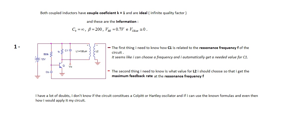
The first thing to understand is how capacitor C1 is related to the resonance frequency f of the circuit. It appears that selecting a frequency allows for the automatic determination of the necessary value for C1. There are uncertainties...
This simple filter utilizes an RC section as the filter element, incorporating a voltage follower to manage other frequencies. The -3 dB point is calculated as 1/(6.28 * RXCV), resulting in a response that drops 6 dB per octave...
The main component is the LG26 one-inch screens integrated with the FSP107-2PS01 two-in-one electrical power package, which utilizes a direct drive CCFL modulator tube. This setup is compatible with screens from other manufacturers, such as Samsung and AU, but...
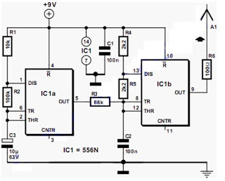
The output frequency alternates between approximately 2100 Hz and 2200 Hz. This unique test signal is easily distinguishable from other potential signals. Resistor R6 is connected to a wire, approximately ten centimeters long, which serves as the antenna. The...
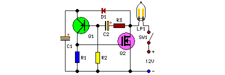
This remarkably straightforward circuit enables the operation of one or two robust 12V 21W car bulbs in a flashing mode using a power MOSFET. Such devices are especially suitable for road, traffic, and yard alerts, as well as in...
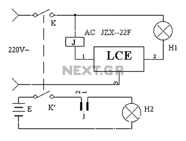
The application circuit operates the device as illustrated below, allowing for intermittent lighting in specific situations (e.g., during surgery). It utilizes an LCE module for blackout emergency lighting, which activates automatically after a power failure, ensuring uninterrupted illumination. In...