
Time Lapse Intervalometer for SLRs with 555 timer IC

The project centers around utilizing the 555 timer integrated circuit (IC) to develop a remote shutter release mechanism for cameras. The 555 timer is a versatile device commonly used in various timing, delay, pulse generation, and oscillator applications. In this context, it can be configured in astable or monostable mode to control the timing of the shutter release.
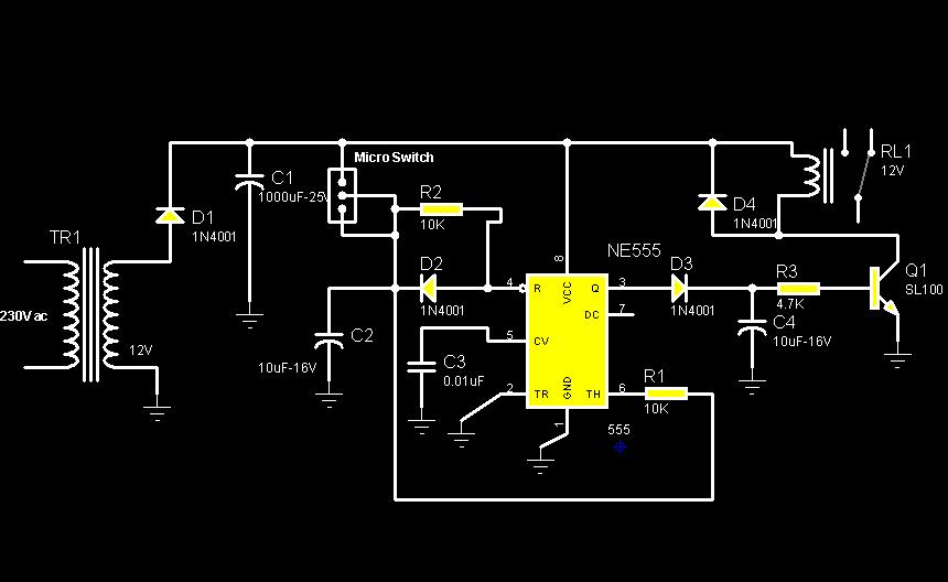
For the schematic, the circuit typically includes the following components:
1. **555 Timer IC**: The core component responsible for generating the timing signal.
2. **Resistors**: Two resistors are used to set the timing interval. The values of these resistors, along with a capacitor, determine the frequency or duration of the output pulse.
3. **Capacitor**: A capacitor is connected to the timing circuit, influencing the charge and discharge times, thus controlling the output pulse width.
4. **Transistor**: A transistor may be used to amplify the signal from the 555 timer, allowing it to drive the shutter release mechanism effectively.
5. **Diode**: A diode can be included to protect the circuit from back EMF generated by the shutter release mechanism, ensuring the longevity of the components.
6. **Power Supply**: A suitable power supply is necessary to provide the required voltage and current to the circuit.
The assembly involves connecting these components on a breadboard or a printed circuit board (PCB), ensuring proper connections according to the schematic diagram. The 555 timer's output pin is connected to the base of the transistor, which in turn is connected to the shutter release input of the camera.
This setup allows the user to trigger the camera shutter remotely, which is particularly useful for long exposure photography or situations where camera shake must be minimized. Proper calibration of the resistors and capacitor values is crucial for achieving the desired shutter timing.
In summary, the project effectively demonstrates the practical application of the 555 timer in creating a remote shutter release system, enhancing the functionality of cameras for various photographic scenarios.This instructable started with my previous camera hack making a remote shutter release. I found a 555 timer tutorial and realized how great it would b.. 🔗 External reference
Related Circuits
The circuit diagram illustrates a rotation sensor that activates a device, such as a motor or buzzer, when the circuit assembly is rotated. The design is based on the fundamental operation of a 555 timer. The rotation sensor circuit utilizes...
This circuit was developed in response to requests from visitors of this website for a timer that can emit a beep after one, two, three minutes, and so on, for jogging purposes. As illustrated in the circuit diagram, SW1...
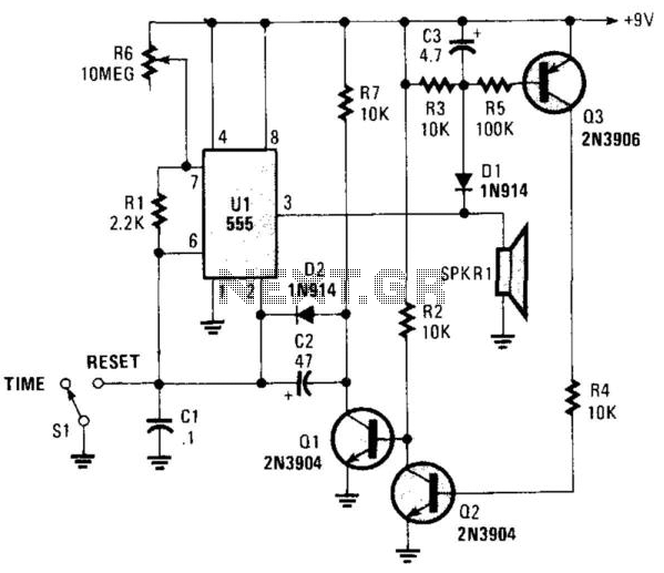
This circuit operates in astable mode and produces a tone at the end of the first period, which can last several minutes. When switch SI is in the time position, transistor Q3 is turned off because pin 3 of...
This electronic timer switch will turn on a light for 100 seconds, turn it off for another 100 seconds, and then turn it on again for 100 seconds after an hour of powering up the circuit. It is a...
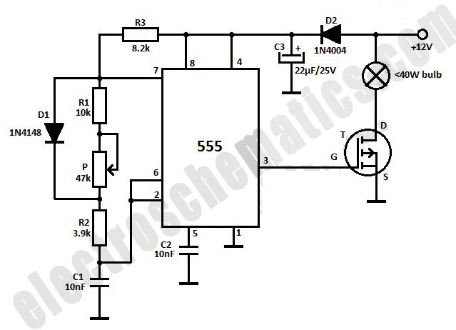
This light dimmer is designed to adjust the brightness of 12V light bulbs utilizing the widely recognized 555 timer, which is configured as an astable multivibrator. The pulses generated by the timer control the power delivered to the light...
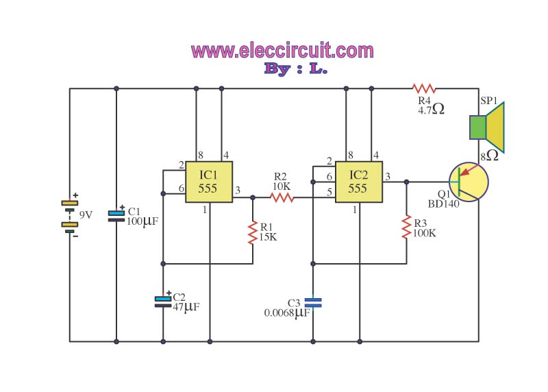
The operation of the circuit is divided into three parts: low-frequency production, high-frequency manufacturing, and low-frequency extension. The low-frequency signal is generated from IC1, which is connected to an astable multivibrator circuit. The frequency is determined by the resistor...