
Time to start reversing relay control circuit

The circuit design incorporates three primary push-button switches: SBi, SBz, and SB3, each serving distinct functions in the operation of the system. SBi, the forward start button, initiates the forward motion of the connected load, while SBz, the reverse start button, allows for reverse operation. SB3, the stop button, halts all operations when pressed.
The time relay units, KTi and KTa, play a critical role in controlling the resistance levels associated with the start buttons. These relays are responsible for timing operations, ensuring that the resistance values are adjusted based on the required operational time intervals. This feature allows for precise control over the speed and direction of the system, enhancing performance and safety.
The configuration of the circuit ensures that pressing the start buttons activates the corresponding relay, which then modifies the resistance in the circuit. This modification influences the current flow to the motor or load, dictating its operational behavior. The design may also incorporate additional safety features, such as interlocks or emergency stop mechanisms, to prevent accidental activation or ensure safe operation during maintenance.
Overall, the circuit is designed for efficient control of a motorized system, allowing for both forward and reverse motion with the ability to stop on demand. The integration of time relays adds a layer of complexity that enhances functionality and adaptability in various applications. Circuit shown in Figure 3-162. in graph. SBi is forward the start button, SBz to reverse the start button, SB3 for the stop button. Start switching resistance levels are contro lled by time relay KTi ~ KTa.
Related Circuits
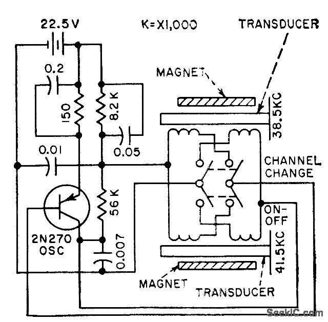
The frequency of a transistor oscillator is regulated by two different lengths of nickel tubing, each containing two coil windings. One coil functions as a driver, while the other serves as a pickup to generate feedback voltage necessary for...
This circuit utilizes a synchronous demodulator to extract a 1 kHz signal from noise and measures its amplitude, with the 1 kHz signal providing a resolution of approximately 60 microvolts per count. The measurements are transmitted via an RS-232...

This light-dependent sensor utilizes light-dependent resistors (LDRs) to detect the presence or absence of light. The alarm remains inactive as long as the light source illuminating the LDRs is constant. However, if the light is interrupted, the alarm is activated. The...
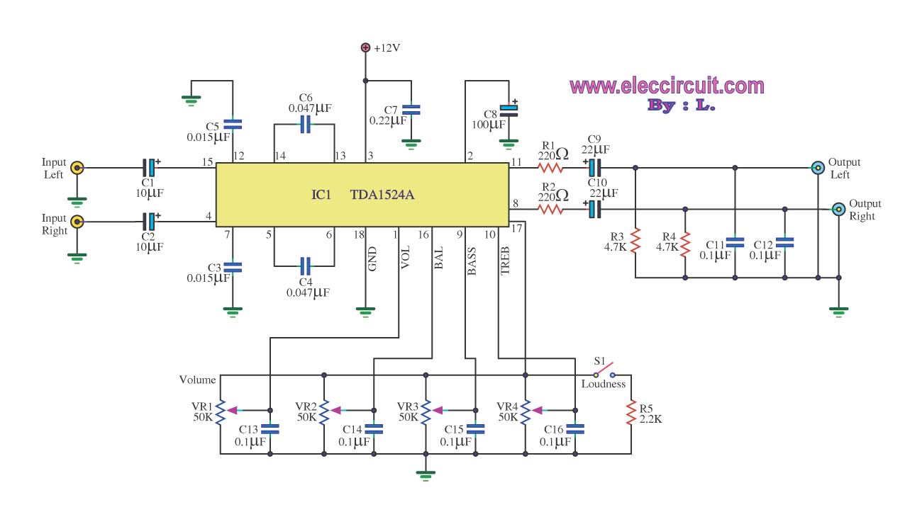
The stereo tone control circuit utilizes the integrated circuit TDA1524A. This IC serves as the central component in the design. The TDA1524A is a versatile integrated circuit designed for audio applications, particularly in tone control systems. It features a dual-channel...
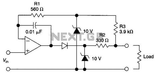
The circuit is designed to drive an external load. A fault condition in the external load circuit could feed excessive current or voltage back into the line drive circuit. If excessive voltage appears from the load, the two zener...
This timer is designed to automatically switch off a portable radio after a set period, allowing users to relax without worrying about battery drain. Resistor R1 and capacitor C1 create a long time constant. When switch P2 is momentarily...