
Timed Beeper

The described circuit functions as a timer with adjustable settings, providing auditory alerts after a designated time interval. The core of the circuit is based on an integrated circuit (IC), specifically IC2, which is responsible for generating an oscillating signal. The oscillation frequency is determined by the resistor R3 and capacitor C1, which are selected to produce a frequency of approximately 4 Hz. This low frequency allows the circuit to beep at a manageable rate, suitable for the intended applications such as games or timed activities.
The user can adjust the timing settings to various intervals, including 15 seconds, 30 seconds, 1 minute, and 2 minutes, among others. This flexibility makes the circuit versatile for different scenarios, such as timing responses in games or monitoring activities like tooth brushing in children.
Activation of the timer is initiated by pressing switch P1, which resets IC2. Upon reset, IC2 begins to oscillate, thereby triggering the alert mechanism after the preset time elapses. The alert is signaled through an auditory beep, which serves as a notification for the user.
Additionally, LED D2 is incorporated into the circuit and is driven by operational amplifiers IC1A and IC1B. This LED blinks in sync with the oscillator frequency, providing a visual indication of circuit operation. The blinking LED not only confirms that the circuit is functioning correctly but also serves as an additional alert mechanism.
Switch SW1 allows the user to select between different timing modes, enhancing the usability of the circuit. This feature is particularly beneficial in environments where multiple timing intervals may be required, such as in cooking or during games.
Overall, the circuit provides a practical solution for timing applications, combining both auditory and visual alerts to effectively communicate the passage of time.Beeps 7.5 seconds after a preset time Adjustable time settings: 15 s. 30 s. 1 min. 2 min. & others This circuit is intended for alerting purposes after a certain time is elapsed. It is suitable for table games requiring a fixed time to answer a question, or to move a piece etc. In this view it is a modern substitute for the old sandglass. Useful also for time control when children are brushing teeth (at least two minutes!), or in the kitchen, and so on. Pushing on P1 resets IC2 that start oscillating at a frequency fixed by R3 & C1. With values shown, this frequency is around 4Hz. LED D2, driven by IC1A & B, flashing at the same oscillator frequency, will signal proper circuit operation. SW1 sele 🔗 External reference
Related Circuits
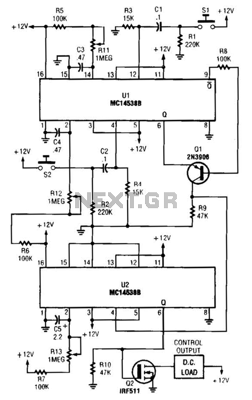
When switch SI is closed, pin 9 of operational amplifier U1 goes low, activating transistor Q1 for a predetermined duration. If switch S2 is closed during this time, transistor Q2 is activated for another predetermined duration. Resistors R1 and...
This is a simple circuit of a beeper using a 555 timer. This circuit can be employed to energize lights, horns, or other signaling devices at any desired interval. The 555 timer is a versatile integrated circuit widely used in...
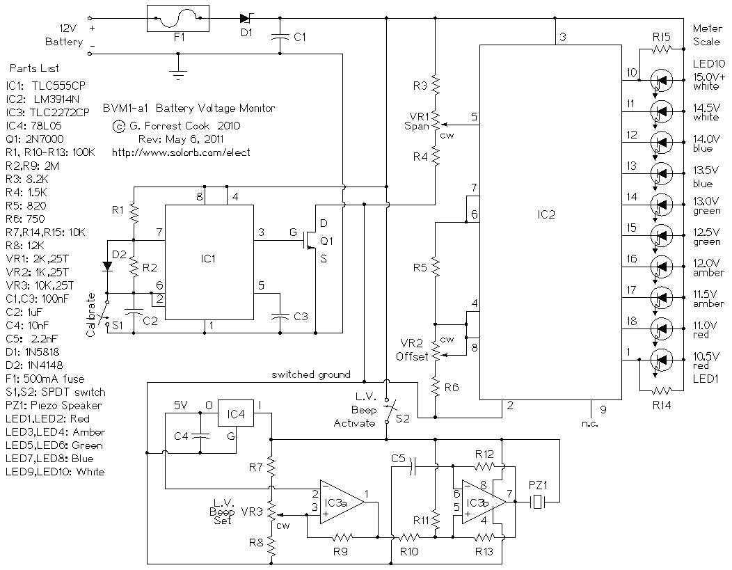
This circuit provides an audible and visual low voltage warning for 12V battery powered devices. When the battery voltage is above the set point (typically 11V), the circuit is idle. If the battery voltage should fall below the set...
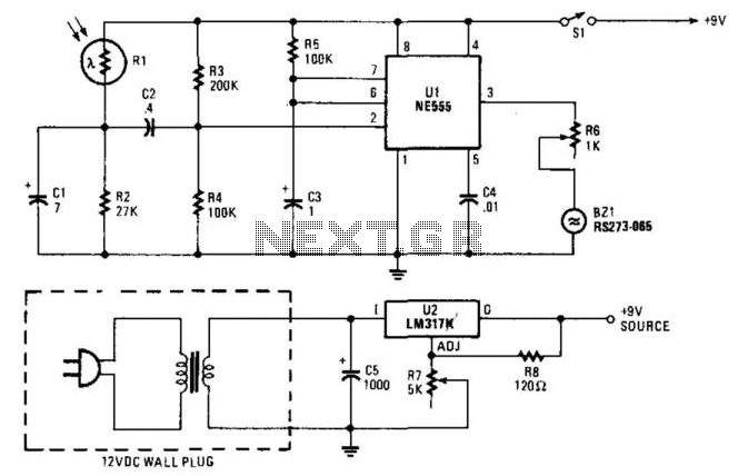
When the light on the answering machine blinks, the resistance of photoresistor Rl increases, triggering the timer (U1) and generating a 0.2-second pulse that activates BZ1. Rl is optically coupled to the LED on the answering machine and is...
A general-purpose hobby circuit for a simple light fence security beeper is presented here. This circuit can be utilized as a door alarm, gate alarm, pathway alarm, and more. It can be powered by any 12 Volt DC power...

The Dutch magazine Audio & Techniek once published an article about one-way loudspeakers that were based on Audax units. Although speakers using just a single full-range unit per audio channel were disregarded in audiophile circles due to high intermodulation...