
Timer Circuit

To create a timer circuit for a pump that operates for a duration of 5 minutes, a simple astable multivibrator or a microcontroller-based solution can be employed.
For a basic timer circuit using discrete components, a 555 timer IC can be utilized in monostable mode. In this configuration, the timer is triggered by a momentary switch to start the timing sequence. The output of the 555 timer will remain high for a duration determined by the resistor-capacitor (RC) network connected to it.
To achieve a 5-minute timing interval, the following component values can be calculated:
1. **Capacitance (C)**: Use a capacitor value of 2200 µF for a longer timing period.
2. **Resistance (R)**: Select a resistor value of approximately 2.2 MΩ. This combination will provide a timing interval close to 5 minutes.
The formula for the time period (T) in a monostable 555 timer is given by:
\[ T = 1.1 \times R \times C \]
Substituting the values:
\[ T = 1.1 \times 2.2 \times 10^6 \, \Omega \times 2200 \times 10^{-6} \, F \approx 5 \, minutes \]
The output from the 555 timer can be used to drive a relay or a transistor that controls the pump. A relay rated for the pump's voltage and current specifications should be used to ensure safe operation.
For a microcontroller-based solution, a simple program can be written to control a digital output pin that turns the pump on for 5 minutes. The microcontroller can be powered by a suitable power source and programmed using an integrated development environment (IDE) specific to the microcontroller being used.
In both designs, it is essential to include protection components such as diodes across the relay coil to prevent back EMF from damaging the circuit and capacitors for power supply decoupling. Additionally, a manual reset or start switch can be included to initiate the timing sequence.
This timer circuit can be housed in a suitable enclosure, ensuring that all components are securely mounted and that the pump is connected safely to prevent any electrical hazards.I don`t the right place to post this but I`ll try my luck here: I`m looking to build a timer for a pump. I want the pump to run for 5 minutes, then.. 🔗 External reference
Related Circuits
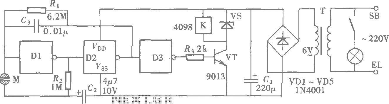
A CMOS gate exhibits high input impedance, which allows it to respond to changes in input levels due to human contact, thereby triggering the toggling of gates. The circuit utilizes this characteristic to create a touch lamp switch. The...
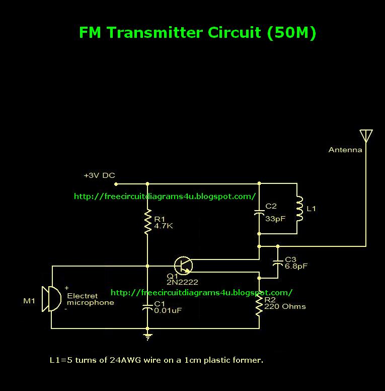
This is an FM transmitter circuit diagram. This circuit uses a 2N2222 transistor, allowing it to operate at 3V and transmit signals up to 50 meters. The FM transmitter circuit consists of several key components, primarily centered around the 2N2222...
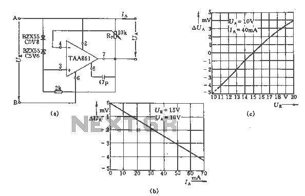
The regulator circuit adjusts the output voltage based on the potentiometer Rp and exhibits linear regulation characteristics. The output voltage Ua varies with the load current Ia, ranging from 0 to 70 mA, as illustrated in Figure (C) for...
To obtain an accurate pressure value, it is essential to eliminate offset errors. Numerous basic circuit designs are employed to remove these offset errors. Offset errors in pressure measurement systems can lead to inaccuracies in the readings, which may affect...
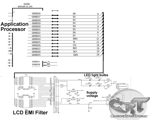
An LCD (liquid crystal display) is an electronically modulated optical device composed of multiple pixels filled with liquid crystals, arranged in front of a light source (backlight) or reflector to generate images in either color or monochrome. The block...
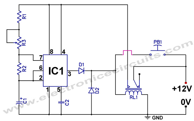
The standard 555 timer circuit consumes power from the battery even when the start push-button (PB1) is not pressed, due to a potential divider created by three 5kΩ resistors within the integrated circuit (IC). This power consumption, referred to...