
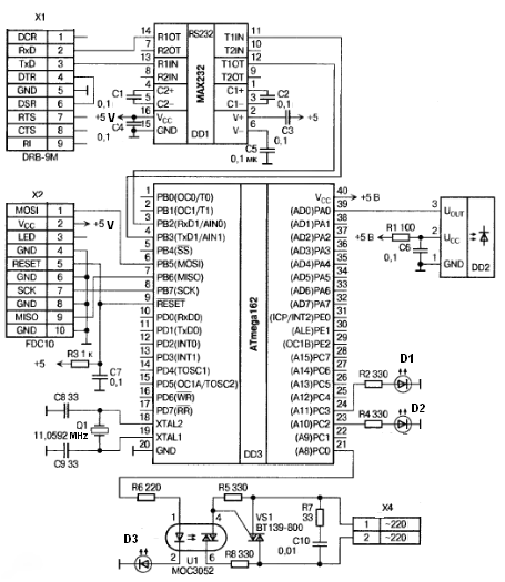
Timing SCR control motor reversing circuit

The circuit operates by utilizing thyristors, which are semiconductor devices that can control power. Thyristors V1, V2, and V7 are connected in a manner that allows for the positive rotation of the motor, enabling it to run in a forward direction. Conversely, thyristors V3, V4, V5, and V6 are configured to facilitate the motor's reverse operation. The switching between forward and reverse is achieved through the control of the single-junction transistor VT1, which acts as a trigger for the thyristors, and the delay circuit incorporating VT2, which regulates the timing of the switching action.
The protection of the thyristors is critical to ensure reliable operation and longevity of the circuit. Resistor R and capacitor C are strategically placed to absorb voltage spikes that may occur during the switching process, thereby preventing damage to the thyristors. This protective measure enhances the robustness of the circuit, allowing it to withstand the stresses associated with frequent motor reversing.
Furthermore, the inclusion of adjustable potentiometers RPi and RP2 provides flexibility in the operation of the motor. By varying the resistance values of these potentiometers, the user can fine-tune the duration of the forward and reverse running times, accommodating different operational requirements. This adjustability is particularly advantageous in applications where precise timing control is essential, such as in automated systems or robotics.
Overall, this circuit exemplifies an effective solution for controlling motor direction and timing, integrating advanced semiconductor technology with practical design considerations for enhanced performance and reliability.Circuit shown in Figure 3-69. It applies to require frequent timing control motor reversing operation of the occasion. Drawing, thyristor Vl, V2 and V7, vs used as a positive control rotation, V3, V4 and V5, V6 used inversion control; motor forward running and reverse running time, respectively, by the extension of single-junction transistor VTi and the like of the circuit configuration and the like by the VTz delay circuit to control; the resistor R and the capacitor C is used for the thyristor protection. Adjust potentiometer RPi and RPz, can change the motor running forward and reverse running time respectively.
Related Circuits
The pulser is designed to switch the mains voltage on and off at intervals ranging from just under one second to up to 10 minutes. This functionality is particularly useful for testing mains-operated equipment over extended periods or for...
A series of shunts and multipliers selected by a switch can be utilized in conjunction with a single basic meter to create a multirange instrument, commonly referred to as a multimeter. This device is capable of measuring voltage, current,...
An IR remote control is a widely used device found with televisions, VCRs, and home theaters. It can also be utilized to control personal devices such as lights and air conditioning. Remote controls operate using infrared (IR) light, which...
In the first circuit, the BC548 transistor is configured as a Colpitts oscillator, with the frequency being adjusted through the insertion of a crystal. A high-quality crystal will generate high-frequency oscillations, and the output at the collector is rectified...
This document explains a simple circuit designed to remotely switch on or off any electrical device using a relay, controlled by a standard TV or VCR. The circuit utilizes a relay as the primary switching element, enabling the control of...
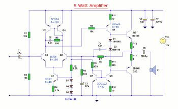
The diagram illustrates a 5W audio amplifier circuit constructed using power transistors BD139 and BD140 for the final amplification stage. This compact amplifier serves as a general-purpose amplifier suitable for applications such as computer audio, radio, MP3 players, and...