
Tiny 1MHz Lowpass Filter Uses No Inductors

The LTC1560-1 integrated circuit is designed for applications requiring precise filtering capabilities, particularly in communication systems. The circuit allows for the selection of two distinct cutoff frequencies, enhancing its versatility in various applications. The filter operates in two modes, with the 1MHz mode providing a flat passband gain up to 0.55 times the cutoff frequency, ensuring minimal signal distortion within the intended frequency range.
The elliptic filter design is notable for its balance between selectivity and transient response, making it suitable for high-speed data communications. The performance characteristics, such as the stopband attenuation of 63dB starting from 2.43 times the cutoff frequency, highlight the filter's ability to effectively reject unwanted frequencies, maintaining signal integrity.
The external phase equalization capability allows for further optimization of the filter's performance. By integrating a dual op-amp configuration with passive components, the circuit can achieve a second-order allpass function, which is critical for compensating for phase distortions that may occur during signal transmission. This feature is particularly beneficial for maintaining the quality of high-speed data signals, as evidenced by the eye diagram analysis that demonstrates the filter's effectiveness in preserving signal shape.
The feedback mechanism employed in the circuit ensures that the DC offset is managed effectively, with the LT1364 operational amplifier playing a key role in maintaining low output DC offset levels. The design incorporates an RC time constant that governs the settling time, which is crucial for applications where rapid signal processing is required.
In summary, the LTC1560-1 filter circuit exemplifies advanced filtering techniques, combining high performance with flexibility for various communication applications, while the additional phase equalization and DC offset management features further enhance its utility in complex electronic systems.A simple circuit for evaluating the performance of the fi lter. The LTC1560-1 offers a pinselectable cutoff frequency of either 500kHz or 1MHz. The fi lter gain response is shown in Figure 2. In the 1MHz mode, the passband gain is fl at up to (0.55)(fC) with a typical ripple of ±0.2dB, increasing to ±0.3dB for input frequencies up to (0.9)(fC). The stopband attenuation is 63dB starting from (2.43)(fC) and remains at least 60dB for input frequencies up to 10MHz.
The elliptic transfer function of the LTC1560-1 was chosen as a compromise between selectivity and transient response. Figure 3a shows the 2-level eye diagram of the fi lter. The size of the “eye” opening shows that the fi lter is suitable for data communications applications.
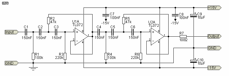
Additional phase equalization can be performed with the help of an external dual op amp and a few passive components. This is shown in Figure 4, where a 2nd order allpass equalizer is cascaded with the IC. The allpass function is achieved through traditional techniques, namely, passing a signal through a low Q inverting bandpass fi lter and then performing summation with the appropriate gain factors.
Figure 3b shows the eye diagram of the equalized fi lter. The input amplifi er stores the DC offset of the IC across its feedback capacitor. The total output DC offset is the input DC offset of the 1/2 LT1364 plus its offset current times the 10k resistor (less than 1.85mV). Upon powerup, the initial settling time of the circuit is dominated by the RC time constant of the DC correcting feedback path; once the DC offset of the LTC1560-1 is stored, the transient behavior of the circuit is dictated by the elliptic fi lter.
🔗 External reference
Related Circuits
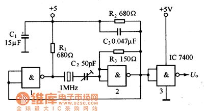
The oscillator circuit consists of a 1MHz quartz crystal resonator and a NAND gate, with the output buffer stage provided by NAND gate 3. This circuit can be utilized for calibrating standard frequency. The described oscillator circuit operates at a...
Electronics tutorial about active high-pass filters, including their high-pass filter frequency response, op-amp voltage gain, and active filter construction. Active high-pass filters are essential components in electronic circuits, designed to allow signals with frequencies higher than a certain cutoff frequency...
A bandpass filter allows a specific range of frequencies to pass while rejecting frequencies that fall outside the upper and lower limits of the passband. The frequencies that are permitted to pass are referred to as the passband, which...
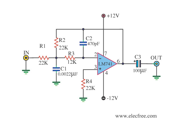
This circuit filters low frequencies below 10 kHz using the highly popular operational amplifier IC uA741. It is convenient for applications that require the conversion of analog signals to digital or vice versa. In digital sound systems, this circuit...
The circuit shown is completely conventional. The Q of the filters has been optimized to allow a higher input impedance than would otherwise be possible, with the final Q of the two filters being almost exactly 0.707 (i.e., a...
Use of IR (infrared) light as a method for wireless communication has become popular for remote control applications. There are a number of different standards for such communication. In this application note, the widely used RC5 coding scheme from...