
TL163 IC For Ultrasonic Remote Control

The TL163 integrated circuit serves as a pivotal component in ultrasonic remote control applications, facilitating the transmission and reception of ultrasonic signals. The circuit typically comprises several key elements: a high-gain amplifier, a detector, and a low-frequency oscillator.
The high-gain amplifier amplifies the weak ultrasonic signals received by the system, ensuring that they are sufficiently strong for further processing. This amplification is crucial for improving the signal-to-noise ratio, thereby enhancing the reliability of the remote control operation. The amplifier is often configured in a non-inverting mode to maintain signal integrity while boosting the amplitude.
The detector circuit is responsible for identifying the presence of ultrasonic signals. It converts the received sound waves into an electrical signal that can be interpreted by the control system. This conversion process is typically achieved using a piezoelectric transducer, which generates an electrical output in response to mechanical vibrations from ultrasonic waves.
Additionally, the low-frequency oscillator generates the carrier frequency used for transmitting the ultrasonic signals. This oscillator is designed to operate at frequencies typically above the audible range, ensuring that the signals remain imperceptible to human hearing while still being effective for remote control applications.
Overall, the integration of these components within the TL163 circuit allows for effective ultrasonic communication, suitable for various remote control tasks, including but not limited to, remote lighting systems, garage door openers, and other automated control systems. Proper design considerations, including component selection and layout, are essential to optimize performance and ensure reliable operation in practical applications.The following circuit shows about TL163 IC For Ultrasonic Remote Control Circuit Diagram. Features:detector, high-gain amplifier, low-frequency .. 🔗 External reference
Related Circuits

This is a small circuit designed for use as a charging controller or voltage limiter. It is particularly useful for creating a solar charger. The assembly of the circuit allows for modifications according to personal preferences. The circuit is...
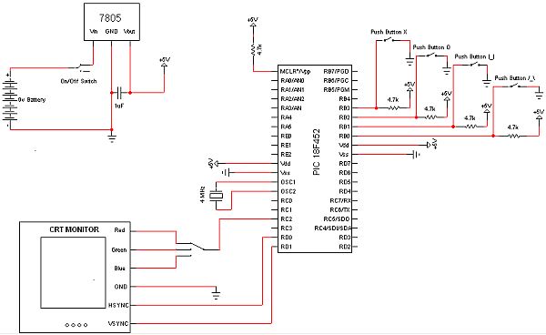
The objective of this project is to develop a device capable of outputting VGA signals to a CRT monitor to display figures, text, and characters. The project involves designing a circuit that generates standard VGA signals, which include separate horizontal...
The 555 IC is wired as an astable and the frequency is constant and independent of the duty cycle, as the total resistance (R charge + R discharge, notice the diode) is constant and equal to 22Kohm (giving a...
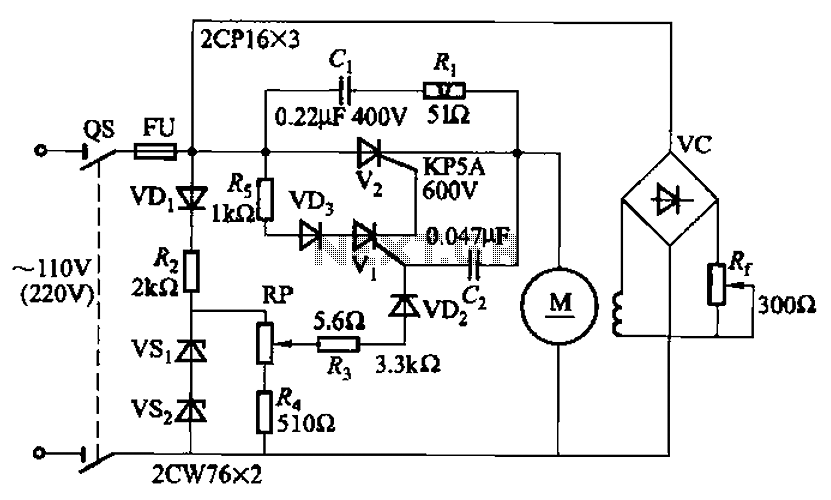
A 100W resistance-triggered motor control circuit designed for arc welding machines. It features an adjustment potentiometer (Rr) that can modify the DC motor excitation current. Additionally, a regulator (RP) is included to adjust the DC motor armature voltage, enabling...
This is a single operational amplifier tone control circuit. The circuit functions as a hybrid low-pass, high-pass, and one-pole filter with both attenuation and gain. The single op-amp tone control circuit utilizes an operational amplifier (op-amp) to manipulate audio signals...
This remote transmits a tone using an infrared LED. This tone is decoded by the receiver. Since the receiver only switches when it "hears" the tone, there are no accidental activations. The described circuit consists of a remote control unit...