
Infa-Red Remote Control circuit

The described circuit consists of a remote control unit and a corresponding receiver unit. The remote control utilizes an infrared (IR) LED to emit a modulated signal, which encodes a specific tone. This modulation allows the receiver to distinguish the intended signal from background noise or interference, ensuring accurate communication between the two devices.
The infrared LED in the remote is driven by a microcontroller or a dedicated tone generator circuit. The modulation frequency can be selected based on the application requirements, typically falling within the range of 30 kHz to 40 kHz. The choice of frequency is crucial as it must be compatible with the receiver's detection capabilities.
On the receiving end, an infrared photodiode or phototransistor is employed to detect the incoming IR signal. This component is connected to a signal processing circuit that includes a band-pass filter, which helps to isolate the desired modulation frequency from any ambient light or other noise sources. When the receiver detects the specific tone, it activates a switching mechanism, such as a relay or a transistor, to perform the intended action, such as turning on a device or triggering an event.
The design ensures that the receiver only activates upon receiving the correct tone, thereby preventing accidental activations caused by false signals. This feature enhances the reliability and efficiency of the remote control system, making it suitable for various applications, including home automation, security systems, and remote operation of electronic devices.his remote transmits a tone using an infa-red LED. This tone is decoded by the receiver. Since the receiver only switches when it "hears" the tone, there are no accidental activations.. 🔗 External reference
Related Circuits

The three schematics illustrate three building blocks for a 10-meter SSB transmitter. These blocks can also be utilized independently as circuit modules for other transmitters. The VFO board incorporates an FET transmission oscillator, with the VFO signal being mixed...

This device offers numerous implementation possibilities due to its wide input voltage range and large maximum output current across a broad output voltage spectrum. It features long battery life and low power consumption owing to its high efficiency and...
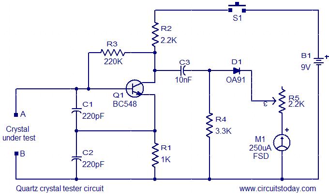
This is a straightforward and cost-effective circuit designed for testing quartz crystals. A Colpitts oscillator is employed using transistor T1. When the crystal is connected between terminals A and B, the circuit generates high-frequency oscillations. These oscillations will only...
A highly effective 1-watt FM transmitter circuit that is easy to construct. The circuit consists of four transistors: one functions as a stable oscillator, followed by a buffer stage to maintain frequency stability during adjustments. Next is a resonance...
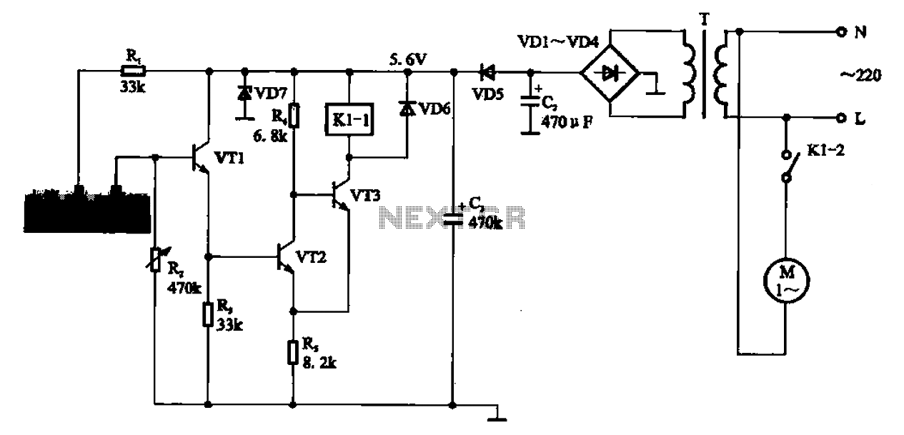
AC motor control circuit for a sprinkler. If the circuit involves an AC motor, it can be designed according to the connection shown in the figure, detailing the work process and the underlying principles of the circuit. The AC motor...
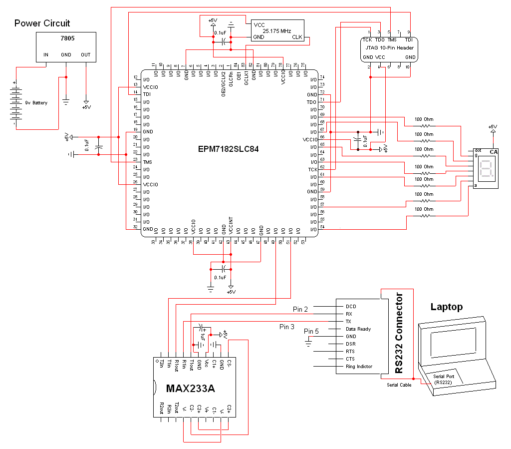
The schematic for this project is a modified version of the CPLD development board schematic. Several new components have been added for this project, and the completed schematic can be viewed below. The main components in the schematic are...