
Tone-actuated relay

The circuit fundamentally utilizes the LM567 tone decoder, which is particularly effective for applications requiring tone detection. The LM567 operates by comparing the frequency of an incoming audio signal with a reference frequency set by the variable resistor. The adjustment of this resistor allows for fine-tuning of the detection range, providing versatility in applications where different frequencies may need to be monitored.
When the input tone matches the adjusted frequency, the LM567's output goes low, signaling that a valid tone has been detected. This output is connected to the base of the 2N3906 PNP transistor, which acts as a switch to control the relay. The relay can be utilized to activate or deactivate larger loads, making this circuit suitable for various control applications.
The 2N3906 transistor is chosen for its capability to handle the current required to energize the relay. It is important to ensure that the relay's coil voltage and current ratings are compatible with the transistor's specifications to prevent damage. Additionally, a flyback diode may be included across the relay coil to protect the transistor from voltage spikes generated when the relay is de-energized.
Overall, this circuit exemplifies a simple yet effective tone detection system, leveraging the capabilities of the LM567 and the switching properties of the 2N3906 transistor to control external devices based on audio frequency inputs.The circuit is built around the LM567 tone decoder IC that requires about 100 millivolts at its operating frequency. The frequency is set by a 10 K variable resistor and can be between 700 and 1500 He When a tone at the set frequency is present, the 567"s output goes low to energize a relay through a 2N3906 PNP transistor.
Related Circuits
The Thermistor, or NTC (Negative Temperature Coefficient) of 10K, is a standard type. Most types will work. The one in the diagram is a 10K model made by Fenwal (#197-103LAG-A01). The resistance lowers as the surrounding temperature increases, which...
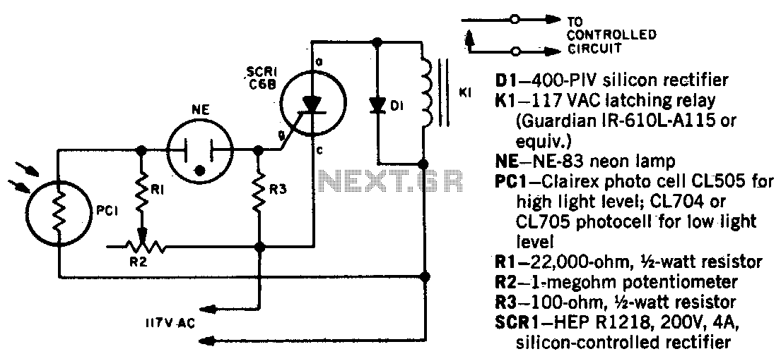
When a beam of light strikes the photocell, the voltage across the neon lamp NE-1 rises sharply. NE-1 turns on and triggers the SCR. K1 is an impulse relay whose contacts remain in position even after the coil current...

This is an automatic battery charger circuit that utilizes the LM324 integrated circuit, which enhances efficiency. It is capable of charging both 12V and 6V batteries, with filtration managed by switch S1. The circuit is designed to stop charging...
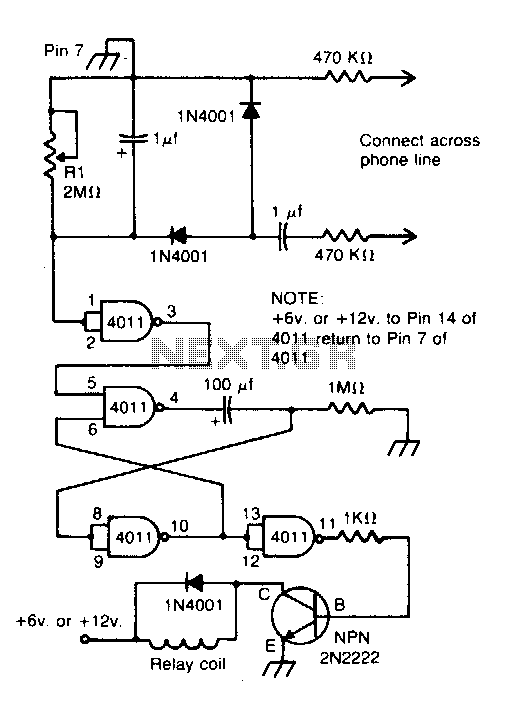
Connected across the bell circuit of a phone, this circuit activates a relay when the phone is ringing. It can utilize delay contacts to operate any bell, siren, buzzer, or lamp. The described circuit functions as a relay activation mechanism...
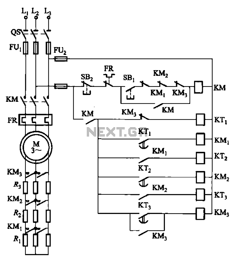
The circuit depicted in Figure 3-159 employs complementary operation three times along with three relay contacts. This is followed by the automatic elimination of the rotor circuit resistance levels, ultimately reducing the rotor winding variable resistor to zero (fully...
This document explains the adaptation of a standard 40 amp car relay, converting it from a "normally open" contact configuration to a "normally closed" contact configuration. While it is possible to perform this modification, automotive relays with "normally closed"...