
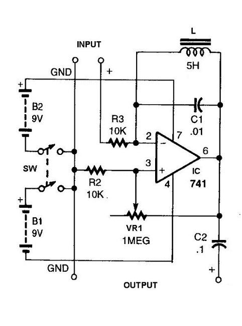
Tunable Crystal radio circuit

The described circuit is a basic crystal receiver designed to operate within the shortwave frequency band. The primary components of this circuit typically include a crystal diode, an inductor, a capacitor, and a pair of headphones as the output transducer. The crystal diode serves as the demodulator, allowing the circuit to convert high-frequency radio signals into audible sound.
The circuit operates by utilizing a tuned circuit formed by the inductor and capacitor, which resonates at the desired frequency of the incoming radio wave. This resonance amplifies the signal, making it more accessible for demodulation by the diode. The output from the diode is a low-level audio signal that can be directly fed into the headphones.
To enhance performance, the circuit may include a variable capacitor that allows tuning to different shortwave frequencies, enabling the user to select various stations. The headphones should be of high impedance to ensure compatibility with the low output power of the crystal receiver.
Overall, this simple crystal receiver circuit is an excellent project for beginners in electronics and radio communications, demonstrating fundamental principles of radio wave reception and audio signal processing.This is a very simple crystal reciever circuit for short wave band and can be used with headphones. 🔗 External reference
Related Circuits
Approximately one watt RMS appears to be a suitable output level, which is also the maximum power that a basic amplifier powered by 12V can deliver to an 8 Ohm speaker. A very low saturation amplifier may reach up...
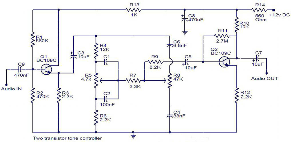
The electrical schematic diagram presented below illustrates a simple two-transistor tone controller audio circuit, which is available for free download. This circuit is based on the well-known Baxandall tone control design. Variations in the values of the transistor components...
This circuit will filter out interference signals and ensure that the signal received from the Morse code station stands out. The described circuit functions as a signal processing system specifically designed to enhance the clarity of Morse code transmissions by...
This circuit is appropriate for any scenario where over-current protection is necessary. An example from the model train hobbyist community illustrates its importance. Experienced model train enthusiasts understand that locating the source of a short circuit can be quite...
This three-band equalizer circuit is an active filter network designed for bass, midrange, and high audio frequencies. It utilizes the LM833 operational amplifier from National Semiconductors. The output of this three-way graphic equalizer is intended to be DC coupled;...
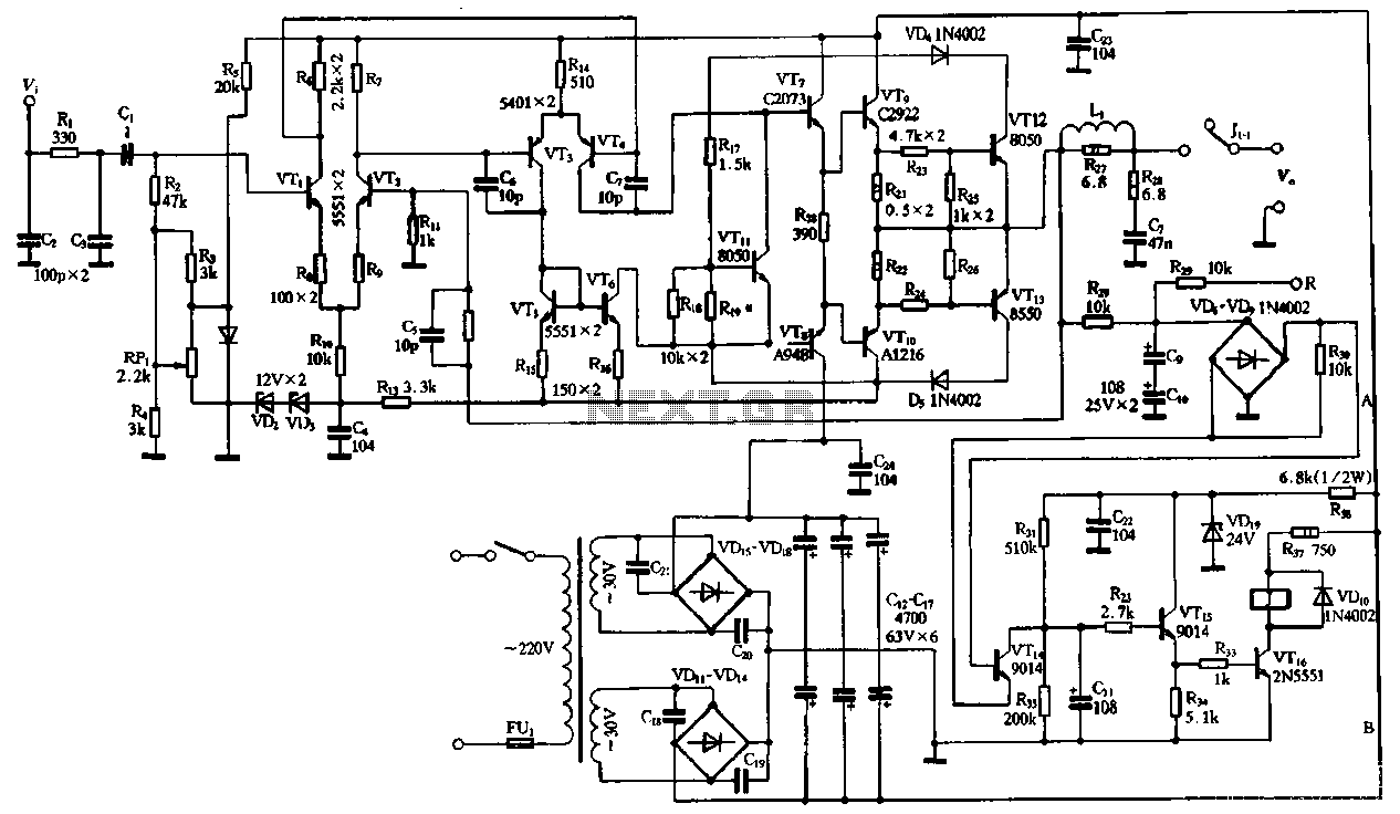
The performance of the amplifiers 2SC2922 and 2SA1216 (or 2SC3264 and 2SA1295) is excellent, featuring good linearity and strong overload capabilities. These devices are utilized as high-fidelity power amplifier stages, demonstrating outstanding performance. The circuit, as illustrated in Figure...