
Notch filter circuit diagram MC33171

The trap circuit is designed to selectively filter out specific frequencies from a signal while allowing other frequencies to pass through. The MC33171 operational amplifier serves as the core component due to its excellent performance characteristics, including a high slew rate and low noise, which are essential for maintaining signal integrity in high-frequency applications.
In this circuit, the notch frequency can be adjusted by varying the values of the capacitor C and the resistors R. The formula for the notch frequency, f = 1/(4RC), indicates that the frequency response of the circuit is inversely proportional to the product of the resistance and capacitance values. Therefore, increasing the capacitance or resistance will lower the notch frequency, while decreasing these values will raise it.
The design typically consists of a feedback loop that incorporates the operational amplifier, capacitor, and resistors. The configuration ensures that the desired frequency is attenuated while minimizing the impact on adjacent frequencies. The high-performance characteristics of the MC33171 allow for precise tuning and effective filtering, making this trap circuit suitable for applications in audio processing, communication systems, and signal conditioning.
Overall, this trap circuit exemplifies the application of operational amplifiers in electronic filtering, demonstrating how component selection and configuration can be leveraged to achieve specific signal processing goals. As shown for the trap circuit. The circuit uses a high-performance op amp device MC33171 constitute trap. The device has a wide band and a high conversion rate. In the illustra ted component values by changing the value of a capacitor C and two resistors R, and other available notch frequency, its value is: f 1/4 RC.
Related Circuits
The 555 timer is utilized as a clock source to drive the RS7490 decimal counter, providing a BCD output to a 7-segment LED display. The clock frequency can be adjusted by changing the value of resistor R1. The circuit operates...
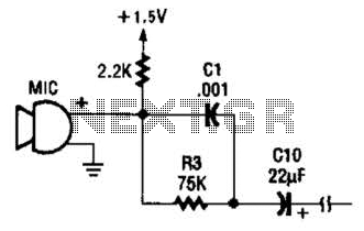
This circuit is suitable for using an electret microphone for various applications. A 1.5-V battery is utilized. CI and R3 provide treble boost and bass cut; they can be eliminated if desired. The described circuit employs an electret microphone, which...
Although a hold feature is standard on most new phones, many users still utilize the original bell phones. For those who require a hold feature, this circuit is particularly useful. It is easy to construct and compact enough to...
This report outlines the operation and adjustment of a Phase Locked Loop (PLL) hum cancellation circuit designed to reduce residual hum from amplifiers. This circuit is particularly useful for Directly Heated Triode (DHT) amplifiers with AC-operated filaments, where a...

This inverter circuit is designed to power electric razors, stroboscopes, flash tubes, and small fluorescent lamps using a 12-volt car battery. Unlike typical feedback oscillator inverters, this design features a separate oscillator from the output stage, allowing for easy...
This digital alarm speedometer circuit allows for the measurement of the acceleration of any moving object, particularly cars and other vehicles. The acceleration is displayed in kilometers per hour (KPH) with a three-digit display. The system operates using laser...