
Touch Switch illuminates LED

More: We start the description at the touch plate. We have already explained how the touch plate works. It consists of two interleaved tracks so that when you touch them with a finger, the resistance between the two tracks reduces.
This action allows more current to flow through the terminals of the touch plate and since it is connected to the base of the NPN transistor, more current flows into the base. Three components are not fitted to this section for this project. They are: 100k, 10n and 10u electrolytic. These are fitted in the second project.
Pick out the components listed in the parts list and lay them on the work-bench. Now you can start assembly. Tick each step as you do it:
( ) Bend the leads of the 47k resistor to 90° and push them down the holes identified by the 47k symbol. Hold the resistor against the board with a finger while soldering so that it stays against the board after soldering. Resistors can be fitted either way around as they are not polarity sensitive devices.
( ) Fit the 1k resistor in the same way.
( ) Fit the 22R resistor.
( ) Fit the red LED so that the longer lead goes down the hole near the edge of the board. The short lead is the cathode and is identified on the board by the line on the symbol.
( ) Fit the NPN transistor so that the C, B and E leads fit down the correct holes. Refer to the large diagrams corresponding to the type of transistor you are using. Push the transistor down so that it is 3mm above the board. Don't fit it any closer otherwise the heat from the soldering operation will overheat the device.
( ) Fit the PNP transistor in the same way.
( ) Cut the hook-up wire into 4 equal lengths and strip the insulation off each end for a distance of 3mm (3/8") and tin the ends with solder. Fit two of the leads to the holes on the PC board marked "Touch Plate" and solder them in position. Solder the other ends to the touch plate. Keep the other two leads for the speaker in project 5. The transistor is a current amplifying device and it will amplify the base current by at least 200 times. The resistance between the collector and emitter leads of the NPN transistor reduces and a "turn-on" circuit is produced for the PNP transistor by the action of the NPN transistor, combined with the 1k resistor.
The circuit operates by utilizing a touch-sensitive plate, which consists of two interleaved conductive tracks. When a finger makes contact with the plate, the resistance between the tracks decreases, allowing a small current to flow. This current, albeit in the microamp range, is insufficient to illuminate an LED directly. Therefore, an NPN transistor is used as a current amplifier, significantly increasing the base current. The gain of the NPN transistor is crucial, as it amplifies the input current by a factor of approximately 200 times.
The circuit assembly begins with the placement of resistors on the printed circuit board (PCB). The 47k, 1k, and 22-ohm resistors are positioned according to their designated symbols on the PCB. The red LED is installed with careful attention to its polarity, ensuring the anode (longer lead) is connected appropriately. The NPN transistor is mounted above the PCB to prevent overheating during soldering, with its collector, base, and emitter leads inserted into the correct holes.
Next, a PNP transistor is similarly installed. The transistors work in conjunction, where the NPN transistor's action reduces the resistance between its collector and emitter, effectively creating a "turn-on" condition for the PNP transistor. This configuration allows for further amplification of the current, facilitating the illumination of the LED.
Finally, hook-up wires are prepared and connected to the touch plate and PCB. This connection allows the touch plate to interact with the circuit, enabling the user to observe variations in LED brightness based on pressure applied to the plate. The circuit's design emphasizes the relationship between touch sensitivity and current amplification, showcasing the practical application of transistors in low-power electronic devices.Our circuit is amplifying the current flowing through your finger (when it touches the touch plate) 10,000 times and this is sufficient to illuminate the LED. The current flowing through your finger (when touching the touch plate) is only a few microamps and this is not enough to illuminated the Light Emitting Diode (LED).
We need an amplifier with considerable gain to get the LED to light and this is what the circuit does. You can alter the brightness of the LED by pressing lightly on the plate and this will show that the resistance of the plate changes with the amount of pressure you exert.
You can also moisten your finger to see how this changes the resistance of the plate and observe the brightness of the LED. We start the description at the touch plate. We have already explained how the touch plate works. It consists of two interleaved tracks so that when you touch them with a finger, the resistance between the two tracks reduces. This action allows more current to flow through the terminals of the touch plate and since it is connected to the base of the NPN transistor, more current flows into the base.
Three components are not fitted to this section for this project. They are: 100k, 10n and 10u electrolytic. These are fitted in the second project. Pick out the components listed in the parts list and lay them on the work-bench. Now you can start assembly. Tick each step as you do it: ( ) Bend the leads of the 47k resistor to 90° and push them down the holes identified by the 47k symbol. Hold the resistor against the board with a finger while soldering so that it stays against the board after soldering.
Resistors can be fitted either way around as they are not polarity sensitive devices. ( ) Fit the 1k resistor in the same way. ( ) Fit the 22R resistor. ( ) Fit the red LED so that the longer lead goes down the hole near the edge of the board. The short lead is the cathode and is identified on the board by the line on the symbol. ( ) Fit the NPN transistor so that the C, B and E leads fit down the correct holes. Refer to the large diagrams corresponding to the type of transistor you are using. Push the transistor down so that it is 3mm above the board. Don't fit it any closer otherwise the heat from the soldering operation will overheat the device. ( ) Fit the PNP transistor in the same way. ( ) Cut the hook-up wire into 4 equal lengths and strip the insulation off each end for a distance of 3mm (3/8") and tin the ends with solder. Fit two of the leads to the holes on the PC board marked "Touch Plate" and solder them in position. Solder the other ends to the touch plate. Keep the other two leads for the speaker in project 5. The transistor is a current amplifying device and it will amplify the base current by at least 200 times.
The diagram below will assist you to see this. The resistance between the collector and emitter leads of the NPN transistor reduces and a "turn-on" circuit is produced for the PNP transistor by the action of the NPN transistor, combined with the 1k resistor. 🔗 External reference
Related Circuits

This simple circuit shown in the schematic diagram activates the switch using sound. This circuit can be used for various applications, such as automatic switching. The circuit utilizes a sound sensor, which is typically a microphone or a piezoelectric sensor,...
This compact design forms a remotely operated switch that receives its control signal via the mains voltage. The switch is operated using the mains remote transmitter described elsewhere in this issue. With this transmitter, a switch should be connected...
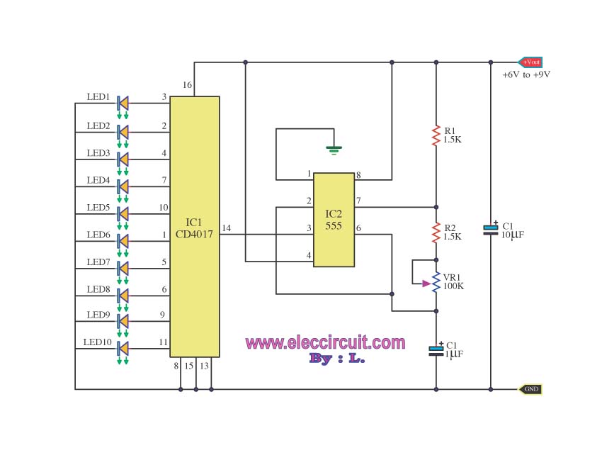
For constructing a 10 LED Chaser circuit, it is recommended to start with this design. It utilizes the widely used and cost-effective IC-4017 decade counter. The 10 LED Chaser circuit is an engaging project that demonstrates the sequential lighting of...
Circuit of a crystal-controlled FM transmitter. The circuit utilizes a crystal oscillator and several power amplifier stages to enhance output power. The crystal-controlled FM transmitter circuit is designed to generate frequency-modulated signals with high stability and precision. At the core...
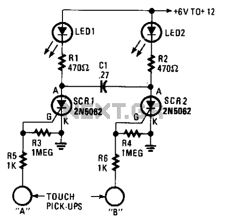
A touch on/off switch circuit is designed using two interconnected sensitive gate SCRs. When one SCR is activated, it forces the other SCR to turn off, creating a toggling effect that allows for an on/off condition for each of...
The circuit is designed for sound and light control of stairway and walkway lighting. It features high immunity and includes soft-start and over-current protection mechanisms. During the day, the photosensitive resistor has low resistance, resulting in a low voltage...