
Toy Motor Drivers

The circuit in question is a simple yet effective design that utilizes a single transistor to control the operation of a permanent magnet DC motor. The transistor acts as a switch, allowing current to flow to the motor when the base is activated. The choice of the 8050 or 8550 transistor is critical, as these components are specifically designed to handle the power and thermal characteristics necessary for motor applications. The distinction between the 625mW and 1W variants is significant; the 625mW version is typically employed in low-power applications, ensuring that the transistor operates within safe limits under normal conditions.
The circuit's design inherently limits the current flowing through the motor when it stalls, thanks to the VCEsat characteristic of the transistor. This feature is particularly advantageous in children's toys, where unintentional stalling can occur frequently. By preventing excessive current flow, the circuit protects the transistor from damage and prolongs the life of the battery, making it a reliable solution for toy manufacturers.
Transient suppression is another crucial aspect of this circuit. The ceramic capacitor placed across the motor terminals serves to dampen voltage spikes generated by the inductive load of the motor, which can otherwise lead to electrical noise and potential damage to the circuit. The choice of a filter capacitor across the power supply can vary based on the specific requirements of the motor and control circuitry, with electrolytic capacitors often providing better performance in terms of energy storage and filtering capabilities.
In summary, this one-transistor circuit serves as an efficient and reliable means of driving permanent magnet DC motors in children's toys, with careful consideration given to component selection, current limiting, and transient suppression to ensure optimal performance and longevity.This is an actual reverse engineered circuit diagram of the one transistor circuit most commonly used to drive Permanent Magnet DC motors in childrens` toys. This type of circuit almost always uses the 625mW version of the ubiquitous 8050 or 8550 transistor. It is vital to note that there are two different varieties of each of these two transistor s, and although they are often stamped with the same part number, they are not interchangeable because one is a 625mW part with a higher VCEsat, while the other is a 1W part with a lower VCEsat. This is very confusing because you often have to run tests on these transistors to tell them apart! The important feature to note about this circuit, is that the maximum power delivered to the motor is normally designed to be limited by the VCEsat of the transistor, and almost never by the HFE or base current.
This works beutifully for childrens toys which are designed around a 3 volt or 4. 5 volt power supply, because whenever the child stalls the motor, this natural current limiting prevents burnout of the transistor and also preserves the battery life. The critical importance of the prior statement can not be overstated. Please not also that the ceramic transient suppression capacitor is always soldered directly across the motor terminals, and note that the filter capacitor across the power supply is just as often a small electrolytic instead of a ceramic disk, depending on the motor transient supression requirements of the control circuitry.
🔗 External reference
Related Circuits

This simple micro-control circuit controls a servo motor according to a 3-state switch. A servo motor acts as an actuator in 3 positions. It has 3 wires, one for VCC, one for Ground, and another one for position control....
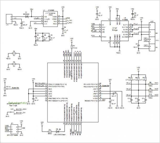
The AVR Microcontroller and high-performance 2.4GHz RF transceiver ATMEGA128RFA1 is an IEEE 802.15.4 compliant single-chip device. It integrates the industry-leading AVR Microcontroller with a top-tier 2.4GHz RF transceiver, offering the highest RF performance for single-chip devices, featuring a link...
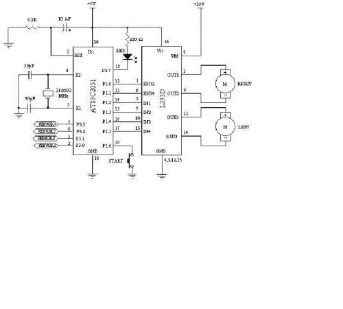
Constructing a robot, or rather a vehicle, that uses two motors. Reference materials regarding the schematics for the circuit design have been obtained, but the current schematics utilize smaller motors that draw less power and operate with a lower...
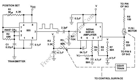
This is a servo system controller circuit designed for remote control of a servo motor. The circuit utilizes a 555 timer and requires only six additional components. The servo system controller circuit operates by generating a pulse-width modulation (PWM) signal,...
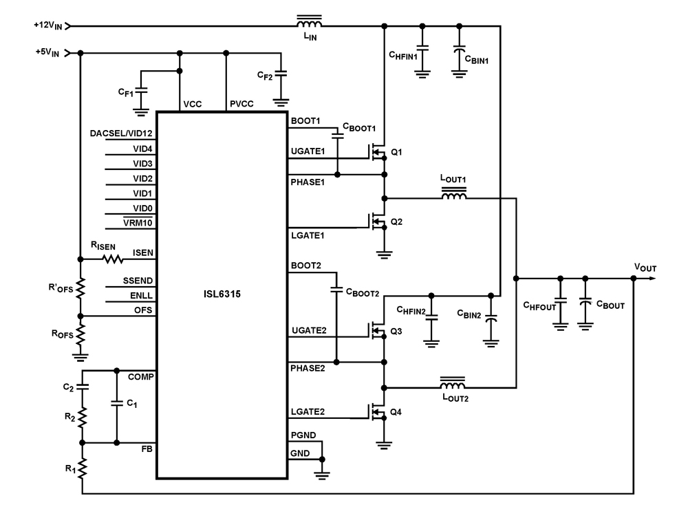
The ISL6315 two-phase PWM control integrated circuit (IC) offers a precise voltage regulation system capable of handling advanced loads ranging from 60A to 80A. Multiphase power conversion represents a significant shift from traditional single-phase converter configurations, which are increasingly...
Schematic of Big Trak's motor driver circuit. The toy includes 9112 and 9113 transistors (and sometimes 2N6715) because the 75494 chip cannot supply enough current to run the Big Trak's motors by itself. The motor driver circuit for the Big...