
Toyota Camry 2007 Car Wiring Diagram

The wiring diagram for the 2007 Toyota Camry is an essential resource for understanding the electrical architecture of the vehicle. It serves as a comprehensive guide for technicians and engineers to navigate the intricate network of circuits that control various functions within the car. The diagram is segmented into different systems, such as the lighting system, power distribution, engine management, and infotainment, allowing for a systematic approach to troubleshooting and repairs.
Each circuit is represented with clear symbols and color codes, indicating the type of wire, connection points, and the components involved. For example, the lighting circuit may include details on the headlight assembly, turn signals, and interior lights, specifying the wire gauge and the connectors used. The engine management system section will illustrate the connections between the ECU, sensors, and actuators, providing insights into how the engine control system operates.
Furthermore, the diagram includes notes on fuse ratings and relay specifications, which are critical for maintaining the integrity of the electrical system. Understanding the layout and connections is vital for diagnosing electrical issues, performing modifications, or integrating aftermarket components.
This wiring diagram is an invaluable tool for ensuring that repairs and modifications are performed accurately, maintaining the vehicle's functionality and safety. It is recommended that users refer to this diagram in conjunction with other service manuals for comprehensive vehicle maintenance and repair guidance.This is the Toyota Camry 2007 wiring diagram applicable for GSV40 and ACV40 Series. This manual provides information on the electrical circuits installed on vehicles by dividing them into a circuit for each system. The actual wiring of each.. 🔗 External reference
Related Circuits
This is a low-cost 150-watt amplifier circuit with a diagram and schematic design utilizing two Darlington power transistors, TIP142 and TIP147. The 150-watt amplifier circuit is designed to provide high power output while maintaining cost efficiency, making it suitable for...
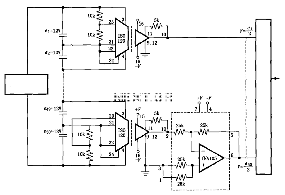
The circuit utilizes the ISO120 and INA105 instrumentation amplifiers to create a battery monitoring system for a 600V battery setup composed of 50 series-connected 12V batteries. This circuit is designed to detect charging and discharging conditions to prevent overcharging...
Common monostable circuit in two configurations: manual start type and start pulse type. It generates a single-shot pulse upon activation. A monostable circuit, also known as a one-shot multivibrator, is a fundamental electronic circuit that produces a single output pulse...
Dodge Durango Fog Light Wiring Diagram. The Dodge Durango fog light wiring diagram provides a visual representation of the electrical connections and components involved in the fog light system of the vehicle. This diagram typically includes the battery, fog light...
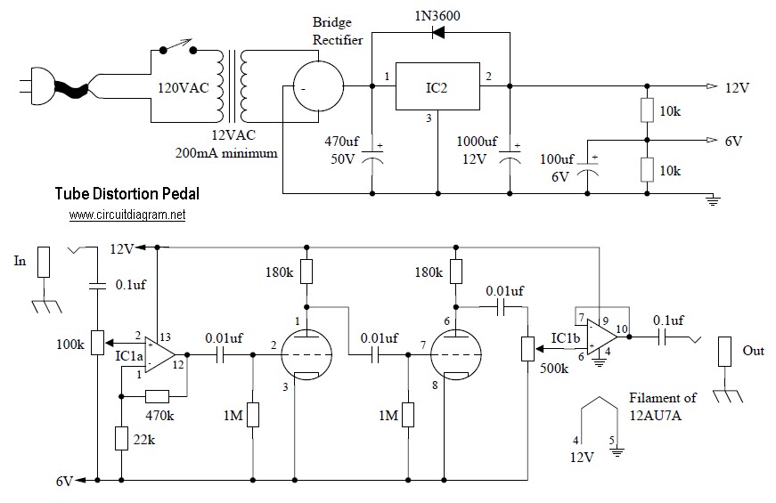
Tube distortion pedal circuit diagram. IC1: 747 dual op-amp; other ICs may be substituted, but the pinout will differ, so the datasheet should be checked. IC2: LM340K-12V voltage regulator. All resistors are 1/2 W. The bridge rectifier is a...
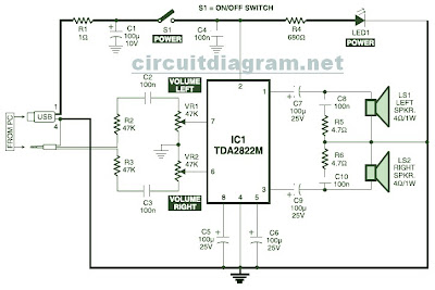
This is the circuit diagram of a USB-powered computer speaker, commonly referred to as multimedia speakers for PCs. The circuit features a single-chip design, operates on a low-voltage electrical power supply, is compatible with USB power from computers, includes...