
simple switch off time delay schematic

The two circuits presented serve to effectively manage the timing of relay activation in response to the ignition or light switch state. The common collector circuit, while simpler due to the absence of a series resistor, limits the voltage available to the relay coil, potentially affecting its performance during activation. In contrast, the common emitter circuit maximizes relay voltage, ensuring reliable operation, particularly in applications where the relay must operate within strict voltage parameters.
For practical implementation, the choice of components—specifically the capacitor and resistor—should be made with careful consideration of the relay specifications and the desired delay duration. The calculated values provide a solid foundation for selecting components, while adjustments may be necessary based on real-world testing. The use of a standard capacitor value, such as 1000 µF, simplifies sourcing components, and adjusting the resistor value allows for fine-tuning of the delay to meet specific requirements. Additionally, it is essential to ensure that the transistor selected can handle the required current and voltage levels, and that the diode used in the circuit is rated appropriately for the application to prevent damage and ensure reliable operation.The two circuits di atas illustrate opening a relay contact a short time after the ignition or ligh switch is turned off. The capacitor is charged and the relay is closed when the voltage at the diode anode rises to 12 volts.
The circuit on the left is a common collector or emitter follower and has the advantage of one less part since a resistor i s not needed in series with the transistor base. However the voltage across the relay coil will be two diode drops less than the supply voltage, or about 11 volts for a 12. 5 volt input. The common emitter configuration on the right offers the advantage of the full supply voltage across the load for most of the delay time, which makes the relay pull-in and drop-out voltages less of a concern but requires an extra resistor in series with transistor base.
The common emitter (circuit on the right) is the better circuit since the series base resistor can be selected to obtain the desired delay time whereas the capacitor must be selected for the common collector (or an additional resistor used in parallel with the capacitor). The time delay for the common emitter will be approximately 3 time constants or 3*R*C. The capacitor/resistor values can be worked out from the relay coil current and transistor gain. For example a 120 ohm relay coil will draw 100 mA at 12 volts and assumming a transistor gain of 30, the base current will be 100/30 = 3 mA.
The voltage across the resistor will be the supply voltage minus two diode drops or 12-1. 4 = 10. 6. The resistor value will be the voltage/current = 10. 6/0. 003 = 3533 or about 3. 6K. The capacitor value for a 15 second delay will be 15/3R = 1327 uF. We can use a standard 1000 uF capacitor and increase the resistor proportionally to get 15 seconds. 🔗 External reference
Related Circuits
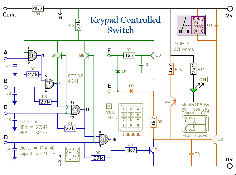
This is a universal version of the four-digit alarm control keypad. The design has been modified to free up the relay contacts, allowing the circuit to function as a general-purpose switch. A single pole changeover (SPCO) or single pole...
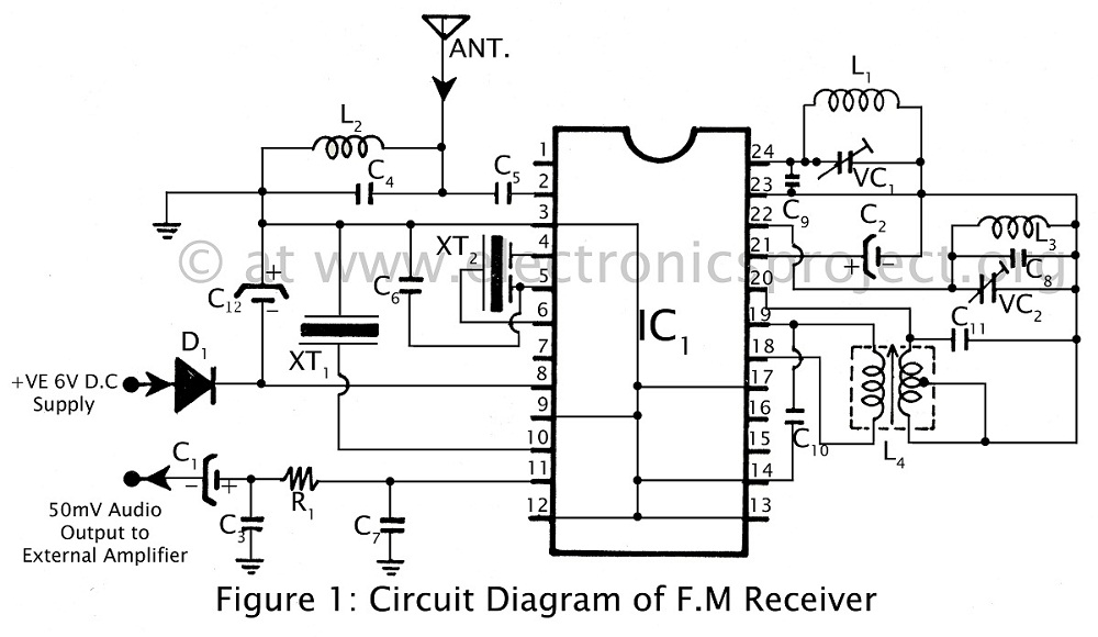
Communication in the FM band is straightforward. This circuit diagram illustrates a powerful FM receiver utilizing a single integrated circuit (IC) that receives frequencies from 88 MHz to 108 MHz within the FM band. The FM receiver circuit described operates...
This circuit allows for the control of any line-powered electrical device, such as a lamp, television, or fan, using any infrared remote control. Many individuals possess a collection of old IR remotes from appliances that are no longer in...
Most cases of infrared remote control failure can be identified by the absence of the pulsed transmitted infrared light. It is very rare that the... Infrared remote controls operate by transmitting modulated infrared light signals that are detected by a...
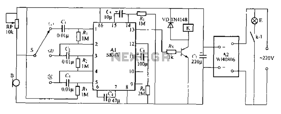
This circuit is a robust light control delay switch with strong anti-interference capabilities. It requires a specific sequence of claps to activate the lamp, which will illuminate for a predetermined duration before automatically turning off. The circuit design is...
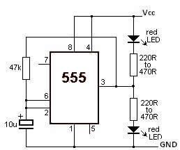
This LED flasher circuit utilizes the 555 timer integrated circuit (IC). The circuit diagram is straightforward and requires only a few external components. When operational, the red LEDs will flash sequentially at a predetermined frequency, similar to the indicators...