
Dimmer Circuit

The light dimmer circuit typically employs a triac or a similar semiconductor device to control the power delivered to the incandescent lamp. The operation of the circuit relies on phase control, where the triac is triggered at a specific point in the AC waveform. This allows the circuit to effectively reduce the average power delivered to the lamp, resulting in a dimming effect.
Key components of a standard light dimmer circuit include a variable resistor or potentiometer, which is used to adjust the phase angle at which the triac is triggered. The circuit may also incorporate an opto-isolator for safety, providing electrical isolation between the control circuit and the high-voltage AC line.
When the variable resistor is adjusted, it changes the timing of the triac's gate signal, thereby modifying the conduction angle of the AC waveform. This results in a change in the brightness of the incandescent lamp. The circuit should be designed to handle the maximum current and voltage ratings of the lamp to ensure safe operation.
In summary, the light dimmer circuit is an essential device for controlling the brightness of incandescent lamps through phase control techniques, making it a valuable addition to residential and commercial lighting systems.Light dimmer circuit is used to control the lamp for arbitrary brightness. This dimmer circuit work for incandescent lamp, not a fluorescent one.? The dimmer. 🔗 External reference
Related Circuits
The servo motor has numerous applications in various fields, including robotics, puppetry, photography, and more. These compact motors can accurately position their output shaft to any specified angle and maintain that position. Most servos have a motion range of...
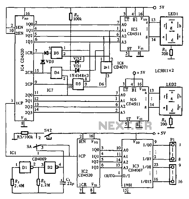
An automatic inspection circuit designed for the simultaneous detection and control of multiple production equipment. This inspection circuit can perform sixteen regular inspections of production equipment. It consists of a pulse generator, multiple inspection circuits, and an automatic inspection...
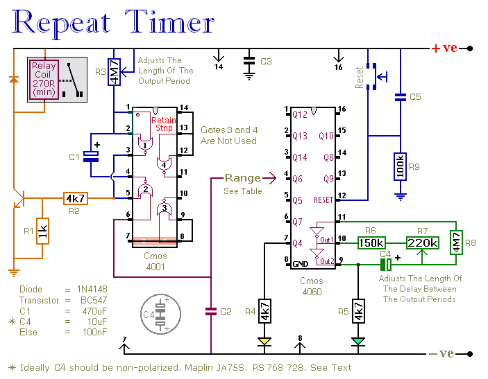
This circuit features an adjustable output timer capable of re-triggering at regular intervals. The output duration can range from a fraction of a second to over half an hour, and it can be configured to recur at regular intervals...
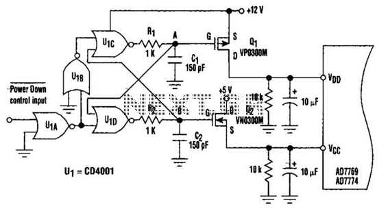
This circuit adds a power-down function to analog I/O ports, such as the AD7769 and AD7774. Additionally, the diodes typically required to protect the devices against power-supply mis-sequencing can be eliminated. In this design, MOSFETs Q1 and Q2 switch...
A video switcher circuit is required to display multiple sources on a single monitor. The circuit schematic below features the MAX454, which serves as the core component of this video switcher. The MAX454 is a video multiplexer-amplifier manufactured by...
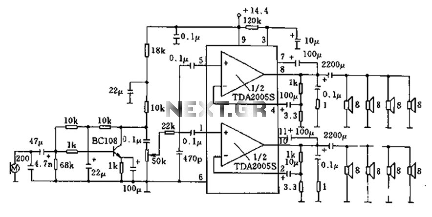
20W bus radio and megaphone circuit utilizing the TDA2005S double low-frequency power amplifier integrated circuit design. The front end can be connected to either a microphone input or a low-frequency radio output voltage amplification stage. Each TDA2005S provides 10W...